Team Minimalists - RDS 2026
Abstract
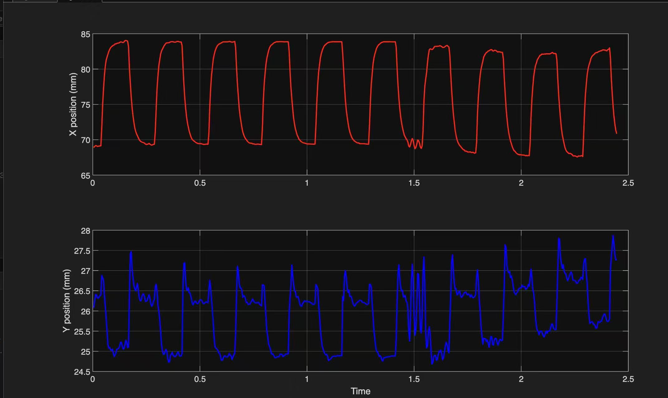
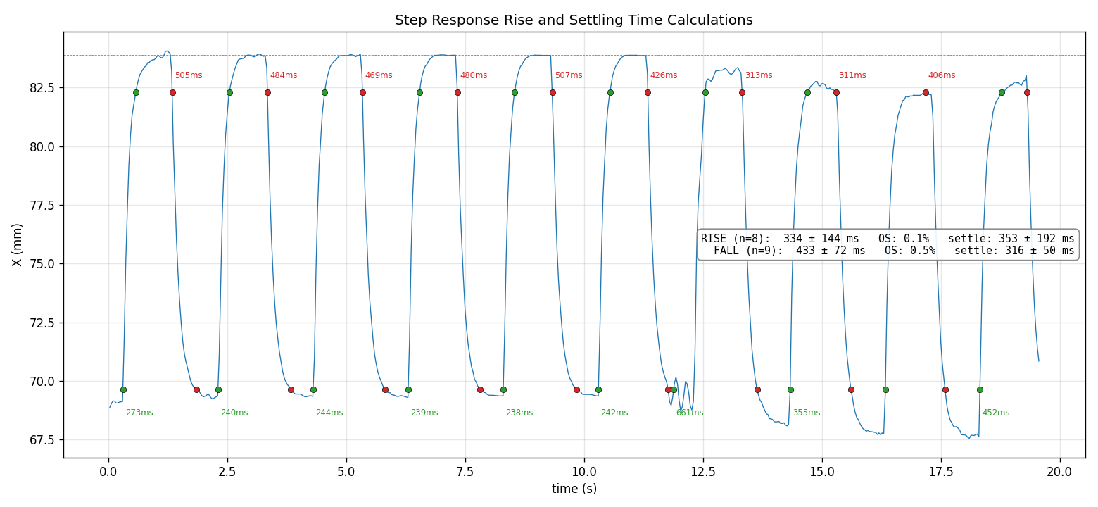
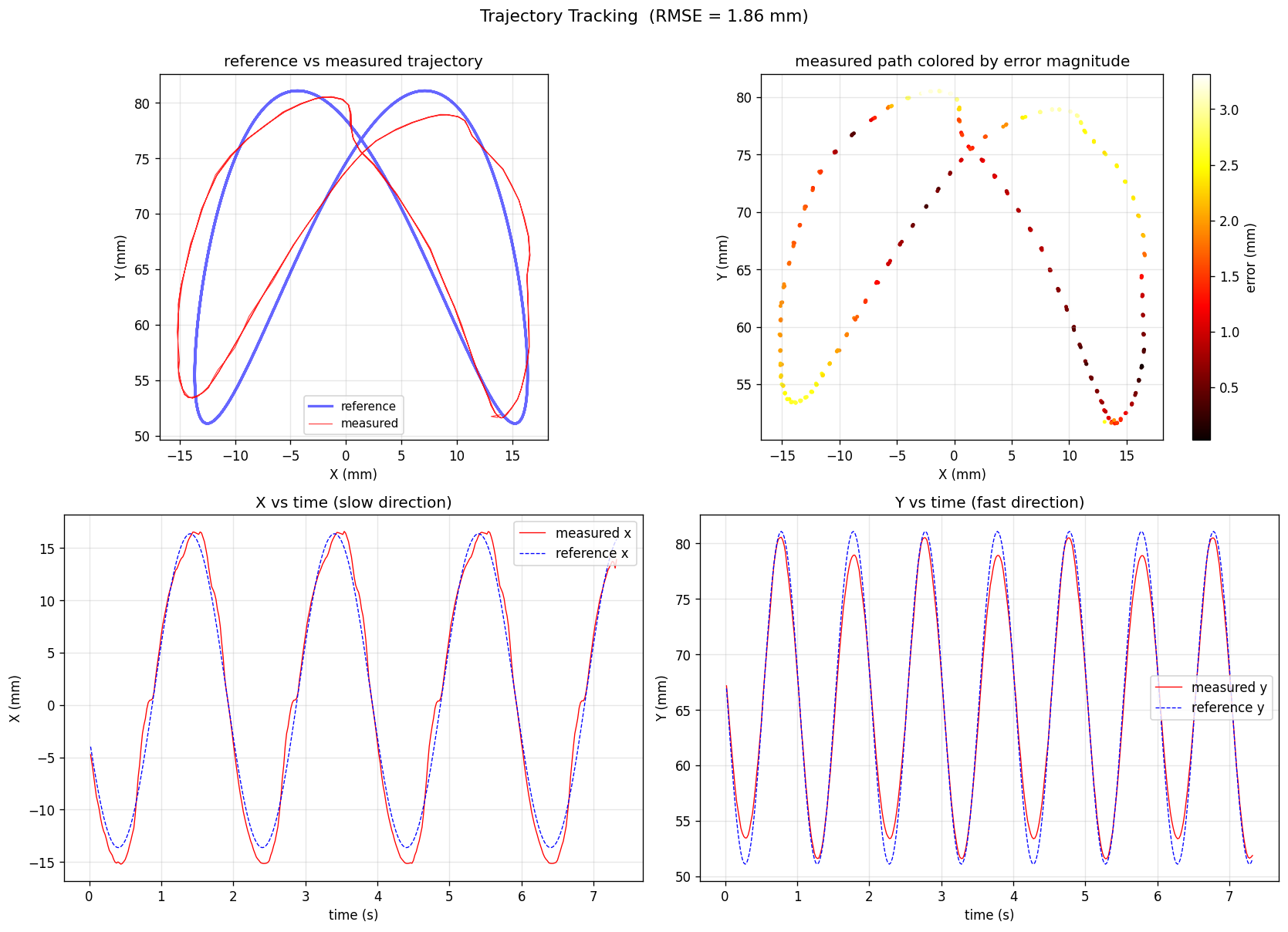
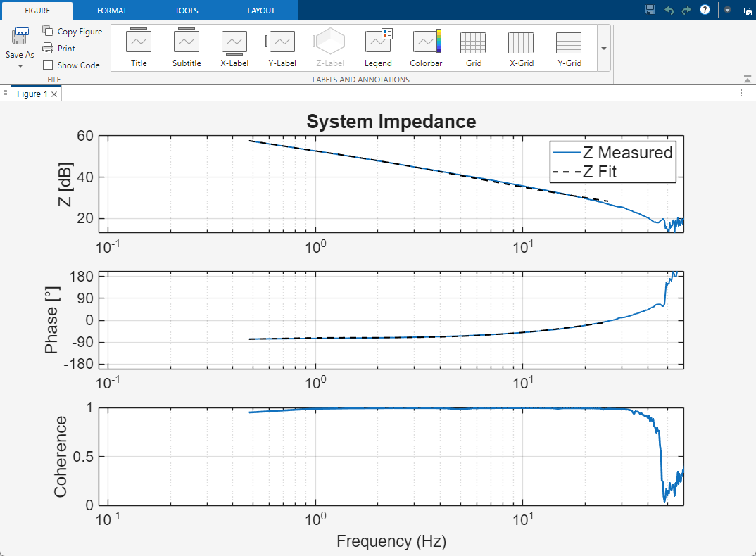
We present a robotic finger developed for the HAND ERC Finger Benchmark, optimized for the Minimalist track: simplicity, maintainability, and repairability. Operating at roughly 1.5× human scale with three active joints (including MCP splay), our design deliberately favors a small, well-understood set of components and accessible assembly over mechanical complexity. Every part is chosen so it can be quickly sourced, reprinted, or swapped, keeping the finger easy to diagnose and fix without sacrificing baseline performance across force, speed, and backdrivability. We characterize the finger on the shared testbed, measuring maximum fingertip force, step position control, Lissajous trajectory tracking, and fingertip impedance, and compare measured results against our analytical model and MuJoCo simulation. The result is a digit that demonstrates how a maintainability-first philosophy can meet competitive performance targets while remaining far simpler to build, repair, and reason about.
Mechanical Design
Read the following PDF for our mechanical design decisions that demonstrates minimalism.
Specs Achieved vs. Team Goals
Goals are shown upfront — click any row to reveal what we achieved.
| Specification | Team Goal | Achieved |
|---|---|---|
| Scale | ~1.5× human finger (gorilla scale) | Click to reveal ~1.5× achieved! |
| Active DOF | 3 active joints max; one splay (MCP abd/add) | Click to reveal 3 DOF achieved! |
| Range of Motion | ~90° in-plane (80° min); ±10° splay | Click to reveal Full range of motion achieved! |
| Speed | ≥ 1 full ROM in 1 s | Click to reveal 1 full ROM in 1 s achieved! |
| Continuous Force | ≥ 20 N at fingerpad extension | Click to reveal 19.7N at fingertip achieved! |
| Max Power (all DOF) | ≤ 100 W total during use | Click to reveal 65W achieved! |
| Emergency Stop | Power-cutting E-stop required | Click to reveal Working E-stop achieved! |
| Budget | ~$5,000 per team | Click to reveal Total cost of 1496.48$ achieved! |
| Full Finger Assembly Time | 15 min | Click to reveal 10 min 6 seconds achieved! |
| Tendon Routing Time | 5 min | Click to reveal 4 min 55 s achieved! |
Bill of Materials
Our design philosophy is minimalism — prioritizing maintainability and repairability over flash. We aim to use as much off-the-shelf products and possible, and most custom parts could be 3D printed with minimal machining required.
| Part / Description | Qty | Source | Cost ea. | Total |
|---|
Physical Demo: Live Reassmbly
Give the wheel a spin — whatever part it lands on, we repair live, right here.
Estimated repair time:
Control Flow Diagram
The finger operates as a finite-state machine on a Teensy 4.1, commanding three CubeMars motors over CAN in MIT mode. After startup and a hard-stop calibration (with tension-sensor zeroing), GPIO interrupts select one of eight control states. Three position states: step, Lissajous, and ellipse, emit Cartesian waypoints, run inverse kinematics to joint angles, and map through tendon lengths to motor position commands; a fourth, flexion-extension, is generated directly in joint space and is terminal (it detaches every interrupt). Three force states: zero, step, and a max-force ramp, close a PID loop around ADS1220 tendon-tension readings, mapping a desired fingertip force to tendon tensions and motor torques. A 500 ms home-position ramp guards every state transition, and the calibration state can be re-entered at any time.Wiring Diagram
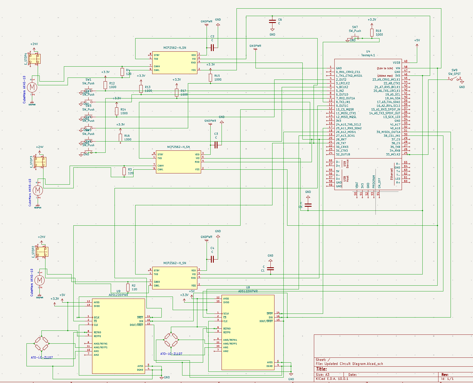
See below for a sample wiring diagram for the circuit.
Calibration
The calibration procedure is a fully automated procedure which calibrates the motor positions to the finger positions as well as zeroes the tension sensors. The sequence starts with motor calibration, in which each motor is individually commanded at a constant velocity until they reach their calibration hardstop (90 for the MCP flexion and DIP flexion motors, and 20 for the splay motor), which is determined by a current spike. This is done twice for each motor, with the encoder position value read three times consecutively during each hardstop contact. All of these encoder position values for a given motor are averaged to find the true position of the hardstop. Next, the motors move the finger to the “home position” (at which all finger angles are zero). There, the tensions are read at each sensor several times and averaged to find the necessary zero offset. The calibration sequence takes a total of 30 seconds. This sequence runs automatically upon running the program, but can always be rerun by simply using the calibration button to switch to the calibration state. During calibration, the finger cannot be switched to another state.
Testing & Characterization: Control
Choose a category, then select a test to view its results.
Maximum Fingertip Force
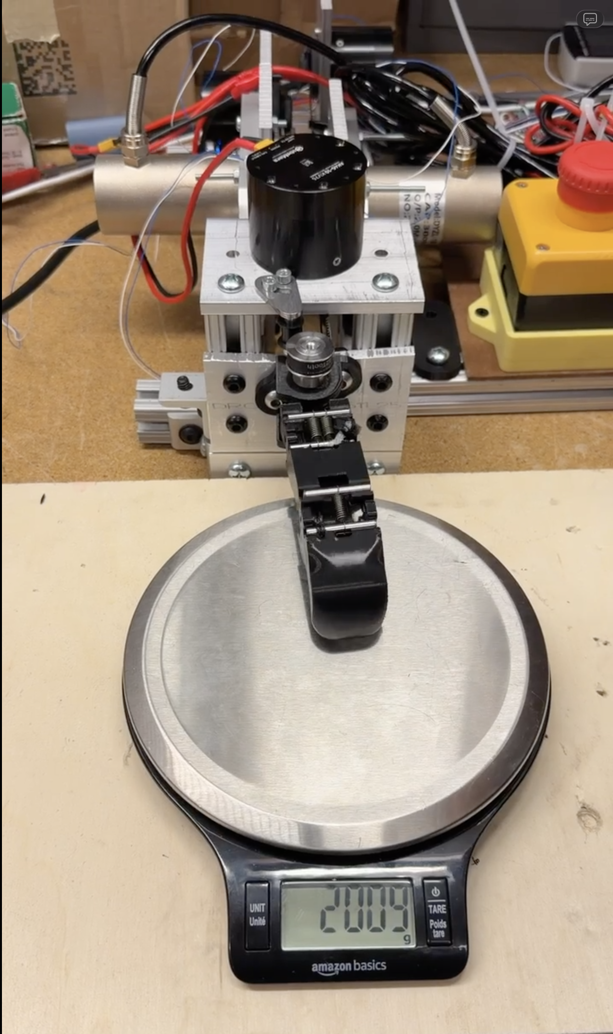
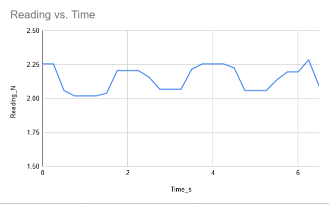
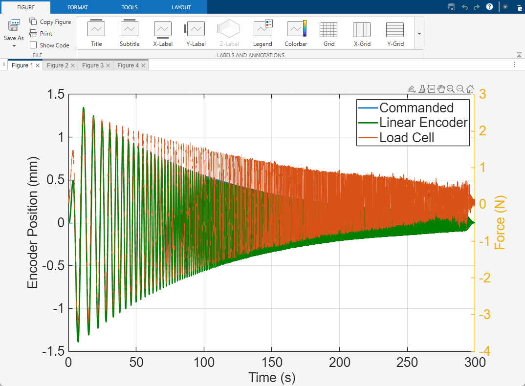
In this test, we determine the maximum force possible for the fully extended fingertip to provide. We did this by ramping up from 0N to 20 N force at the fingertip over a period of 45 seconds. The measured max force the fingertip provided is 19.7 N before failure.
Maximimum Fingertip Force
Testing & Characterization: Mechanical
Select a test to view its results.
Snapfit Lifespan Testing
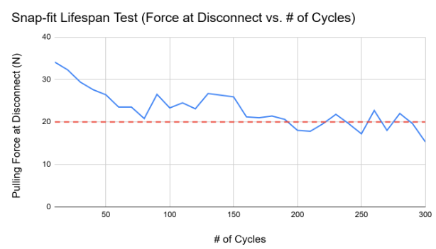
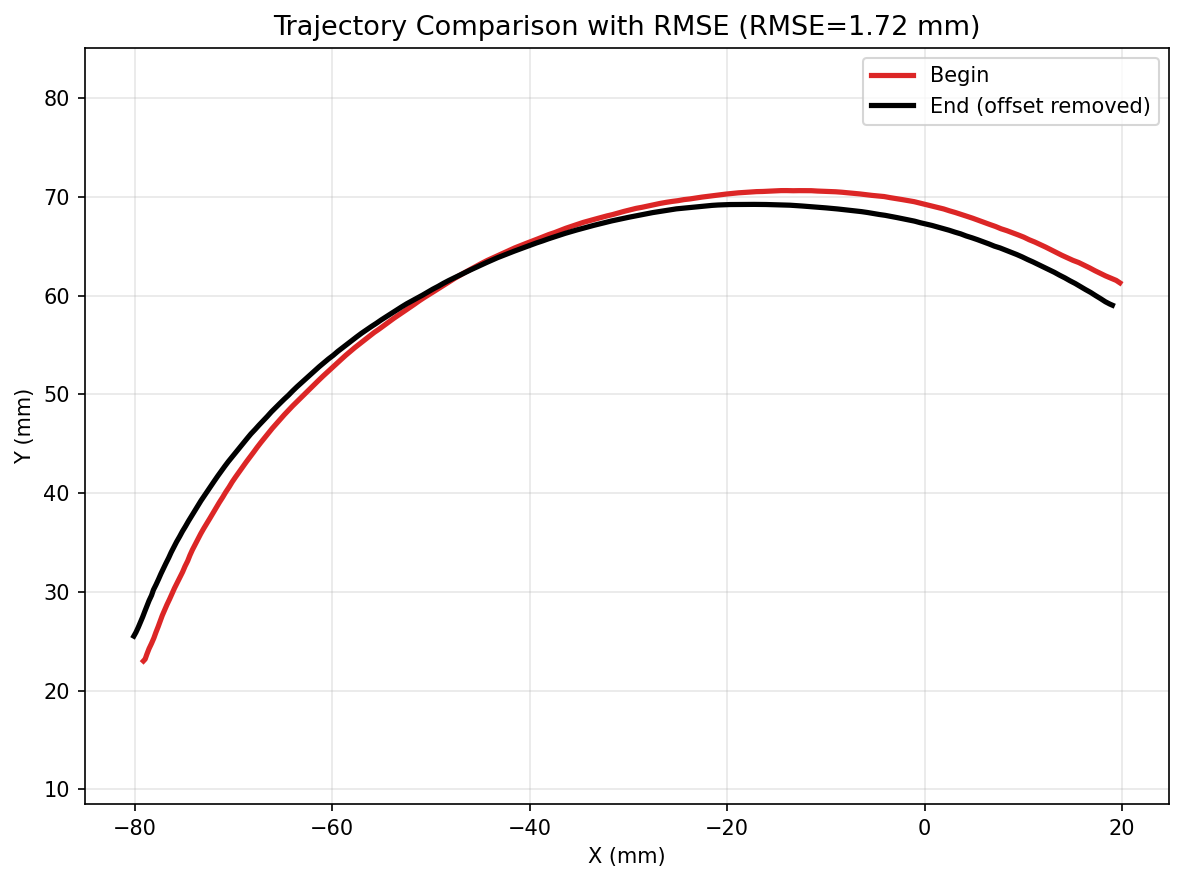
The snap fit lifespan test seeks to validate the total number of cycles that the finger’s snap fits can withstand before failing. This is important because many of the finger’s critical features are assembled via snap fits. If the snap fits wear too quickly, the overall lifespan of the finger will be reduced as its joints become increasingly susceptible to popping apart under normal operation. To measure the lifespan of the finger’s snap fits, we will push in and then pull out a singular snap fit until it takes less than 20 N of pulling force to pop the snap fit out of place. Our goal for this test is to reach 300 cycles of assembly and disassembly (which spans 30 measurements) without failure in the snap fit. We believe that 300 cycles of assembly/disassembly is much greater than what would be seen in real-world use; therefore, surviving this many cycles will validate the long-term durability of the finger’s critical snap-fit joints. Testing results showed reasonable degradation.
Snapfit Lifespan Testing Results
Our Team
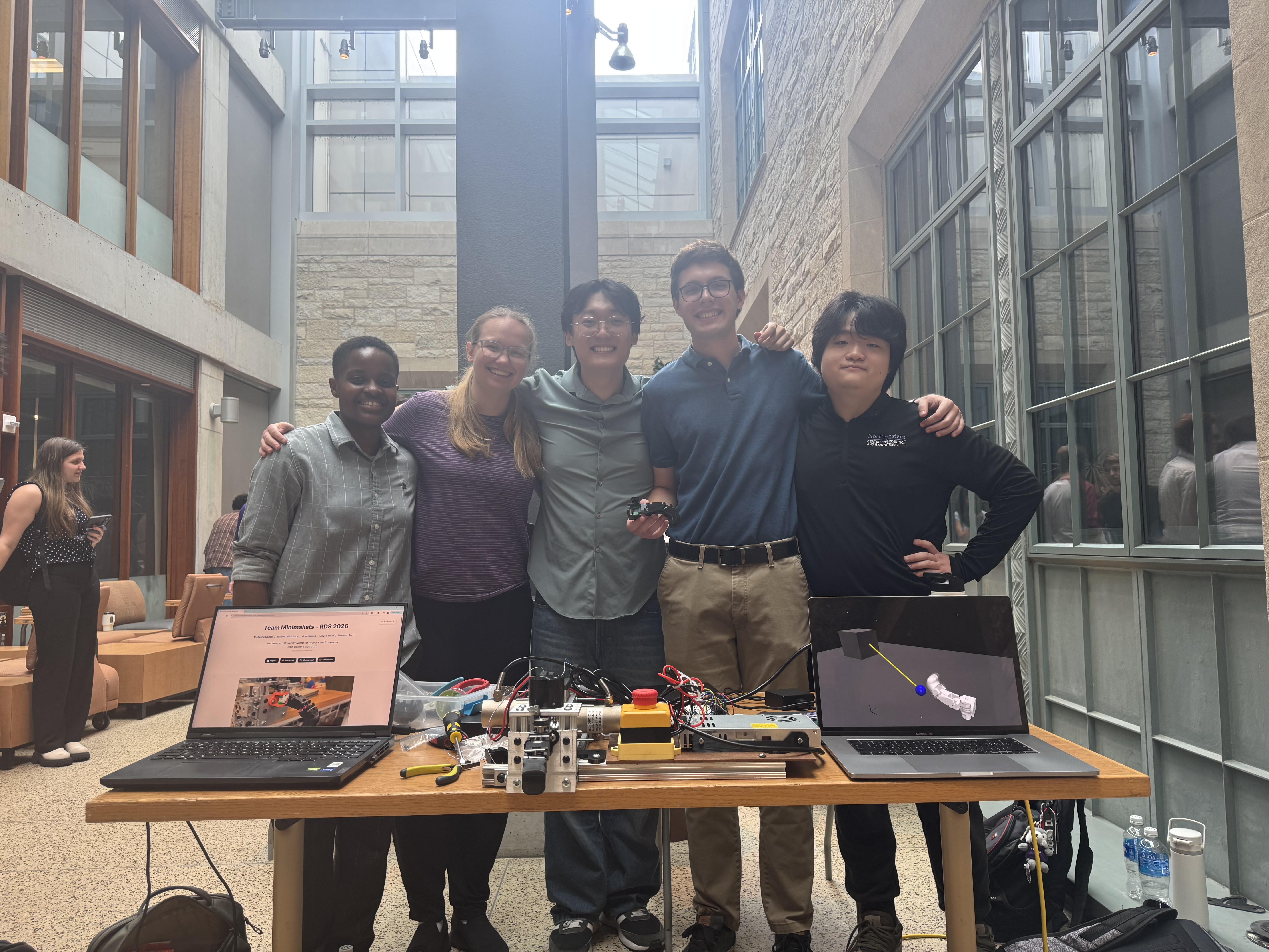
We are Team Minimalists, a group of Northwestern engineering students who designed a robotic finger for the HAND ERC Finger Benchmark with a focus on simplicity, maintainability, and repairability.
Please feel free to contact any of us for any questions or additional information about the project.
Acknowledgments
We are grateful to the many people who supported this project along the way. We thank Professor Ed Colgate, Raphael Cherney, and Sairam Umakanth for guidance and feedback throughout Robot Design Studio, and the staff of the Northwestern University Center for Robotics and Biosystems for access to lab space, equipment, and technical advice. We also thank Nick Marchuk for his help throughout this project and letting us use the Mechatronics Lab, and Tony Shilati for extensive help throughout testing.
Finally, we thank our classmates and everyone who tested, questioned, and encouraged our work during the studio.