03 — Design
CAD, Schematics & Assembly
All mechanical design was completed in OnShape. Below are key views including the exploded assembly, tendon routing diagram, friction reduction features, and sensing architecture.
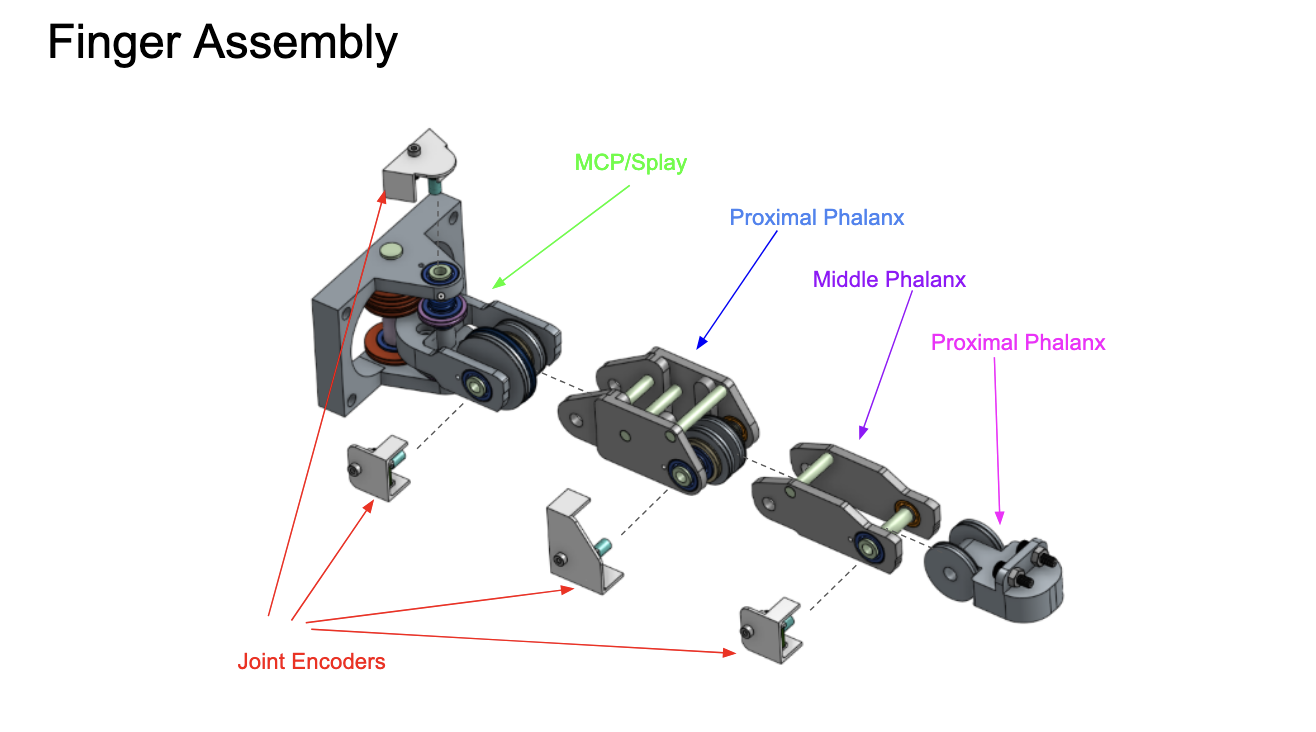
Exploded CAD view showing phalanx links and joint encoders.
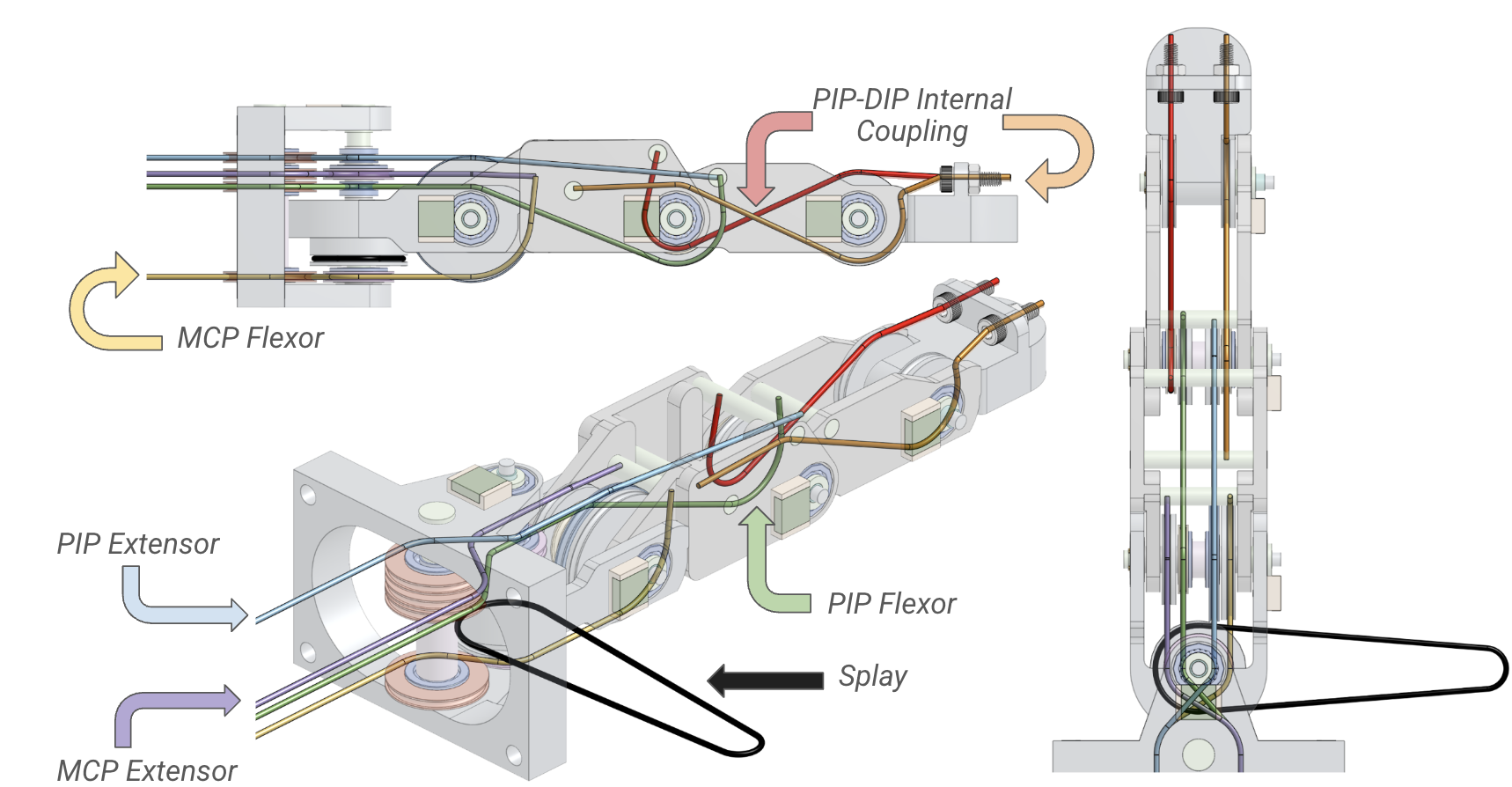
Seven-tendon color-coded tendon routing: MCP Splay (black), MCP Flexor (yellow), MCP Extensor (purple), PIP Extensor (blue), PIP Flexor (green), PIP-DIP Internal Coupling Pair (red and orange).
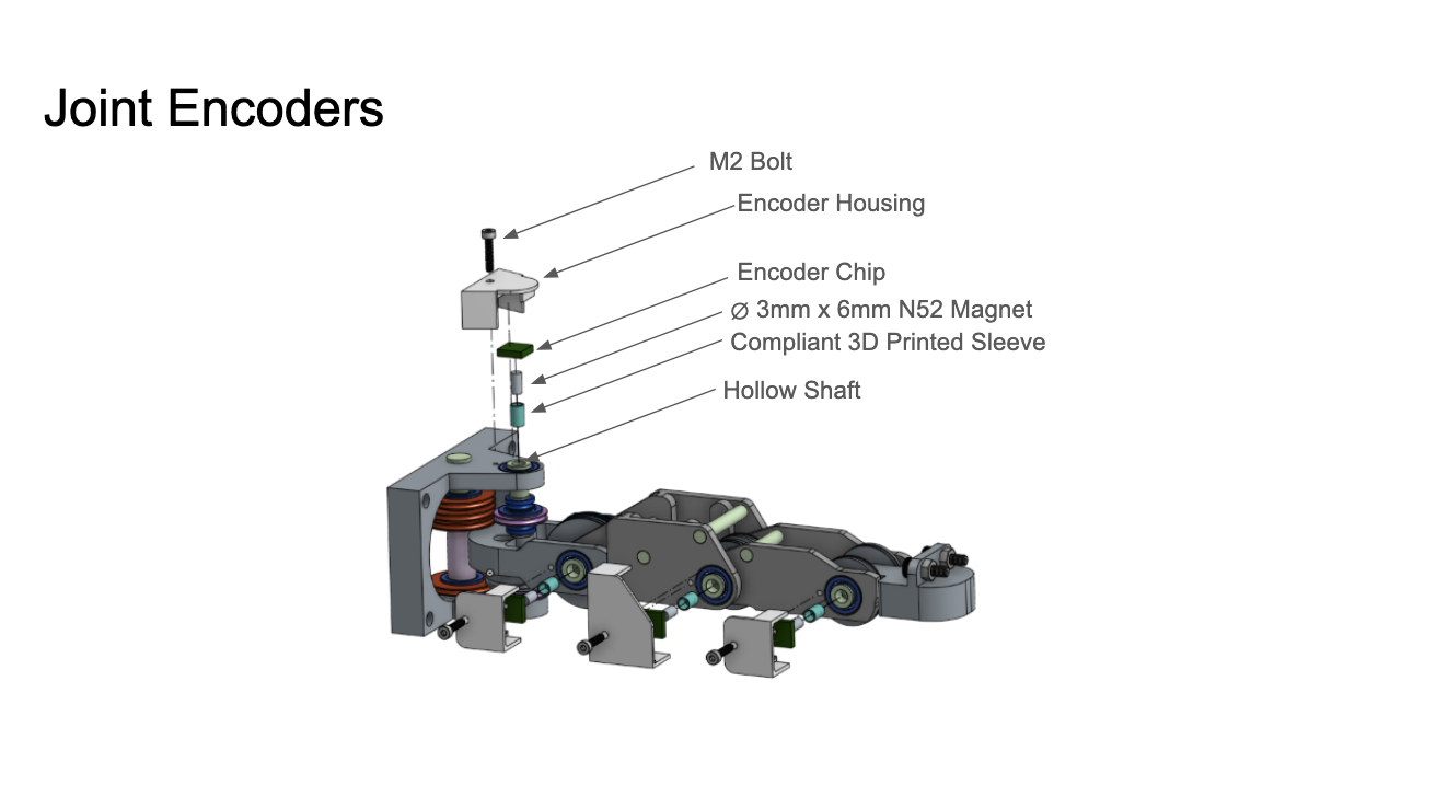
Joint encoder CAD assembly view.
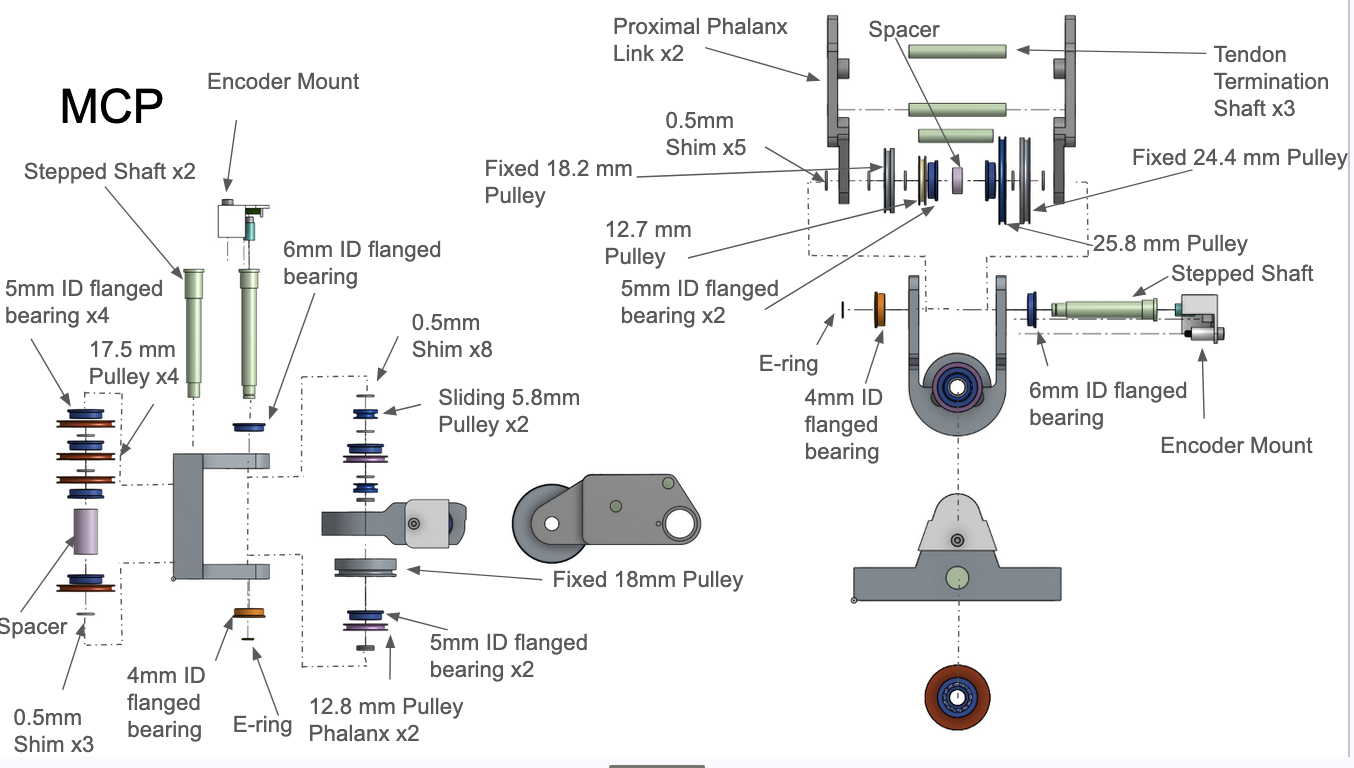
MCP CAD joint exploded assembly view.
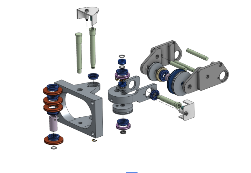
MCP and finger base plate CAD view.
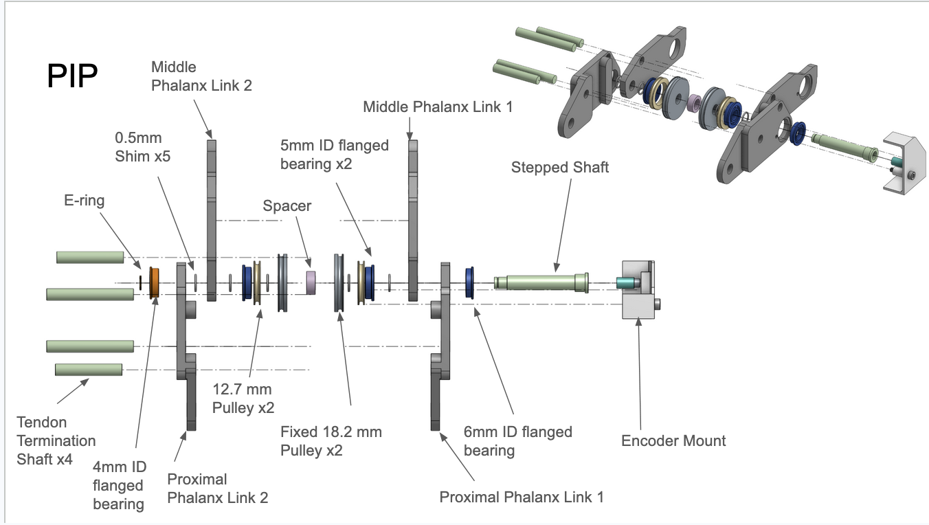
PIP CAD exploded assembly view.
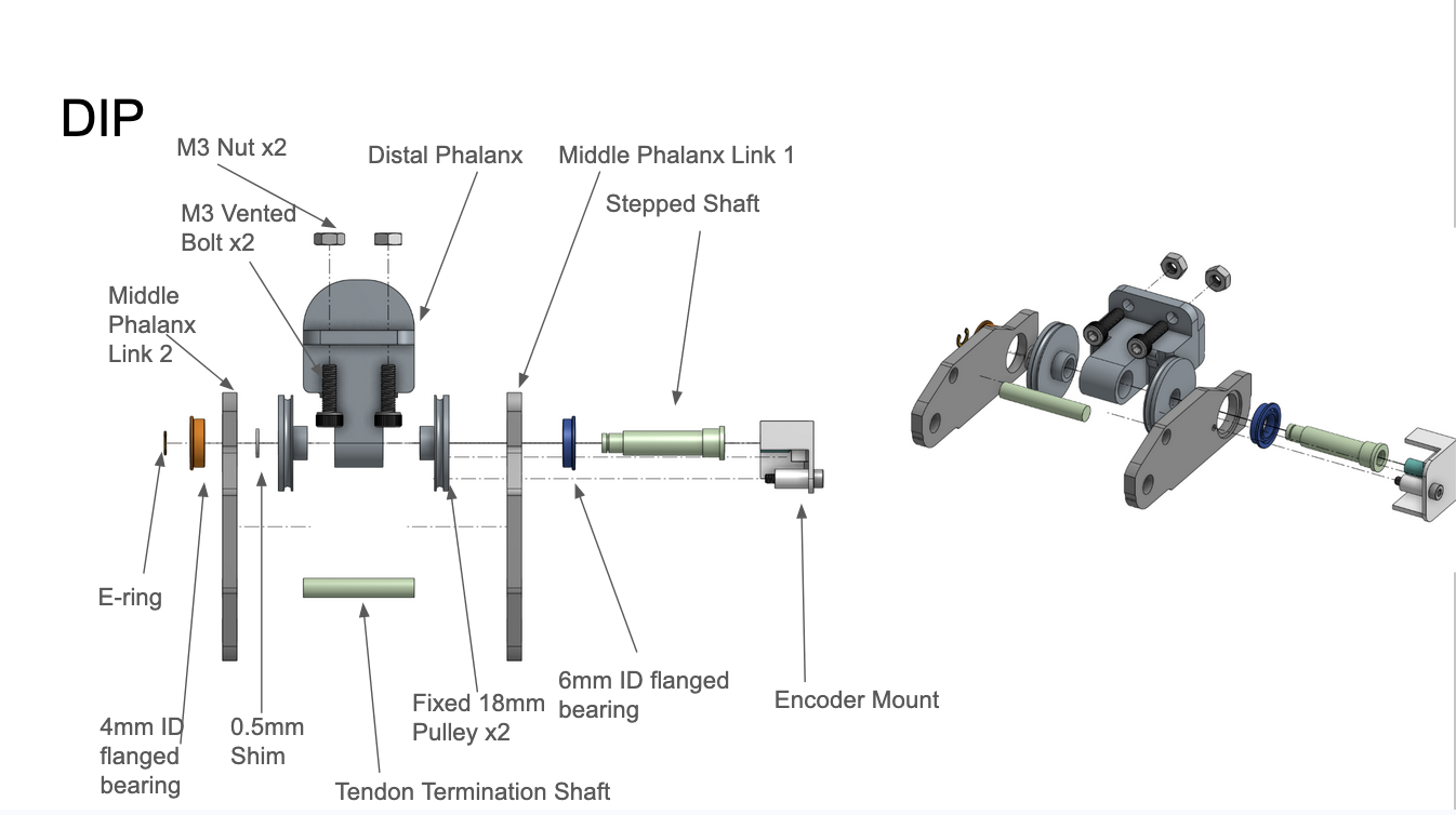
DIP CAD exploded assembly view.
04 — Bill of Materials
Components & Procurement
| # | Component | Specification / Part # | Qty | Unit Cost | Total | Supplier | Notes |
|---|---|---|---|---|---|---|---|
| Structural | |||||||
| 1 | Phalanx Links + MCP Base | Aluminum 6061 | 1 | 1 | $375.95 | Outsourced + Custom machined | JLCCNC, CNC milled; bearing seats reamed to size |
| Motors + Encoders + Drivers | |||||||
| 2 | Brushless DC Motors | [DB42S01] | 5 | 1 | $72.90 | Nanotec | Rated Torque 50.13 Nmm |
| 3 | Planetary Motor Gearbox | GP42-S2-26-SR | 5 | 1 | $203.80 | Nanotec | Reduction Ratio 25.62 |
| 4 | Motor Encoder | NME3-SSI-X14-12-C2 | 5 | 1 | $136.50 | Nanotec | SSI 16-bit resolution |
| 5 | Controllers + Drivers | ODrive Pros | 5 | 1 | $229.00 | ODdrive Robotics | Motor Controllers |
| Bearings & Shafts | |||||||
| 6 | Ball Bearings | [ Part # — TBD ] | 22 | 22 | $275.88 | McMaster-Carr | Bearings Numbers: 104, 106, 685 |
| 7 | Shafts | 12L14Carbon steel | 3 ft. | 3 ft. | $13.32 | McMaster-Carr | Pre Ground Stock, Machined into stepped shafts or tendon termination shafts |
| 8 | E-Rings | E-Rings | 100 | 1 | $3.43 | McMaster-Carr | Axial shaft constraint |
| 9 | Carbon Steel Shim Stock | Shims | 1 | 150 x 2500 x .5 (mm) | $30.93 | McMaster-Carr | Machined for shims for spacers |
| Tendons & Termination | |||||||
| 10 | Dyneema (UHMWPE) Cord | .8 mm dia, 250 lb tensile | 100 ft. | 1 ft. | $0.09 | Emma's Kites - Amazon | <1% stretch at working load |
| 11 | Vented Bolt (Coupling Tendon Tensioner) | Vented Bolt | 1 | 2 | $17.15 | McMaster-Carr | Mechanical tightening to account for hysteresis |
| Pulleys | |||||||
| 12 | Pulley Stock | Aluminum — custom machined | 22 | 1 | $0.00 | Custom | Idlers and Fixed pulley with groove to guide tendons. Material Provided by Ford Shop |
| Sensing & Electronics | |||||||
| 13 | Magnetic Angle Encoder Chips | MA782 | 4 | 1 | $3.73 | Monolithic Power Systems | Axially-mounted; 0.5° resolution target |
| 14 | Press-Fit Magnets | [ N45 6 X 3 mm. Magnets] | 4 | 1 | $3.29 | McMaster-Carr | Housed within stepped shafts and a 3D printed holder |
| 15 | Custom PCB | Custom Board for MA782 Sensors | 1 | 4 | $0.30 | Custom / JLCPCB | Joint Encoder signal routing and serialization |
| 16 | Fingertip Force Sensor | A101 Tekscan | 1 | 1 | $9.44 | Tekscan - Supplier: Digikey | Piezoelectric Fingertip Force Sensor |
| 17 | DCDC Module | DCDC Converter | 1 | 1 | $6.16 | Digikey | Changes output of (something) into somehing |
* Some quantities and costs not shown, see link to complete BOM in RDS Drive. Materials 3D Printed from Northwestern's labs not included.
05 — Demonstrations
Demo Videos
Team Demos
Simulation Demos
Simulation Demos
Simulation Demos
Simulation Demos
06 — Experimental Results
Tests & Measurements
All tests listed below are either completed or planned. Plots, images, and videos will be added as results are collected.
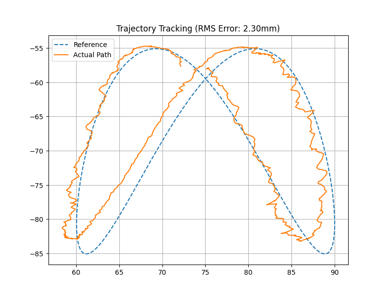
Test 01
Trajectory Tracking Test
Measure the finger ability to trace a Lissajous figure on the main plane of motion x-z (no splay) bounded by a 30mm x 30mm region with a frequency of .5 Hz.
Test 02
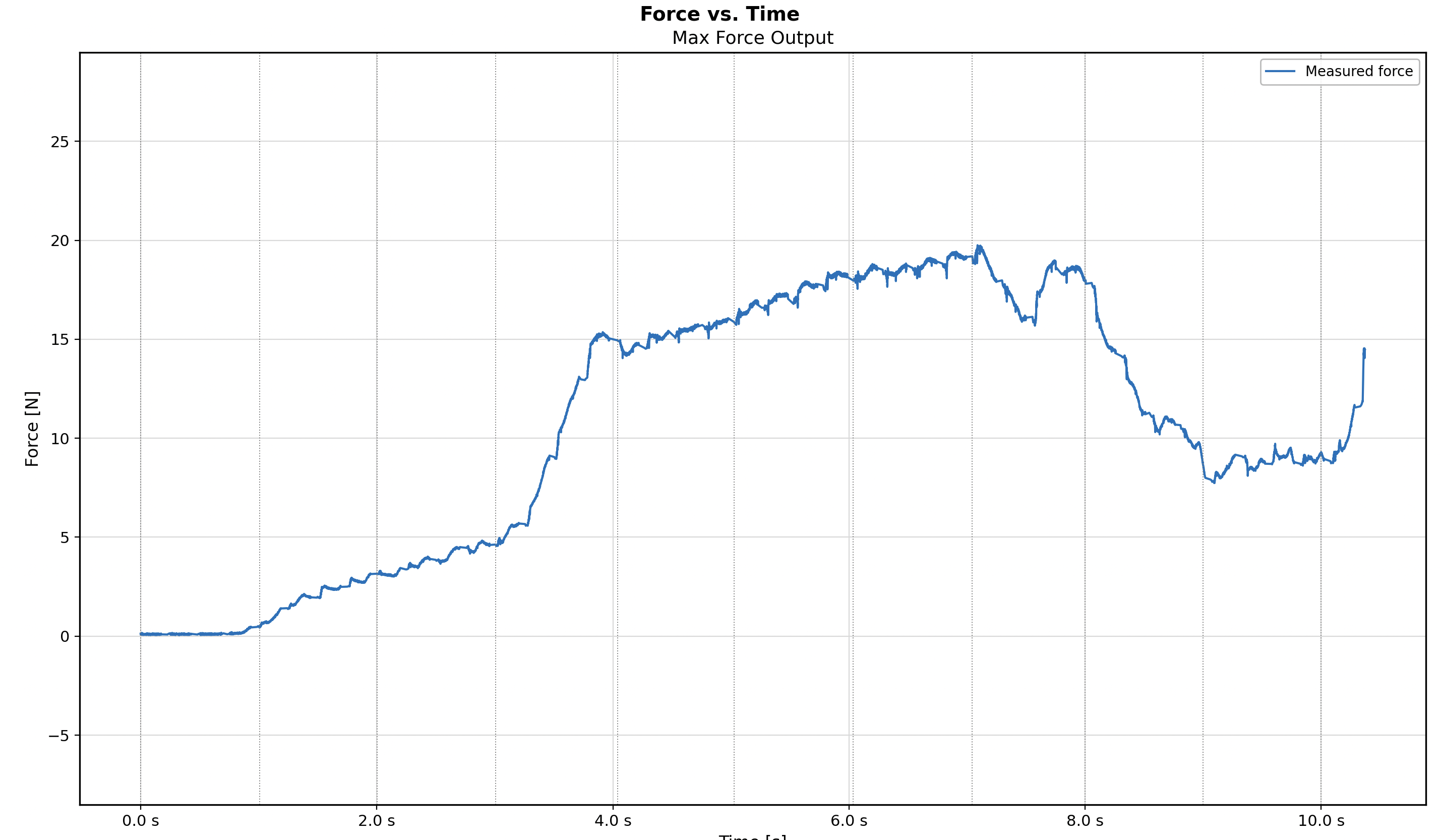
Fingertip Force Output
Measure continuous fingertip normal force at full tendon tension. Target: ≥ 20 N. Setup: load cell at distal phalanx tip, motors at rated current. Peak Force 19.7 N
Test 03
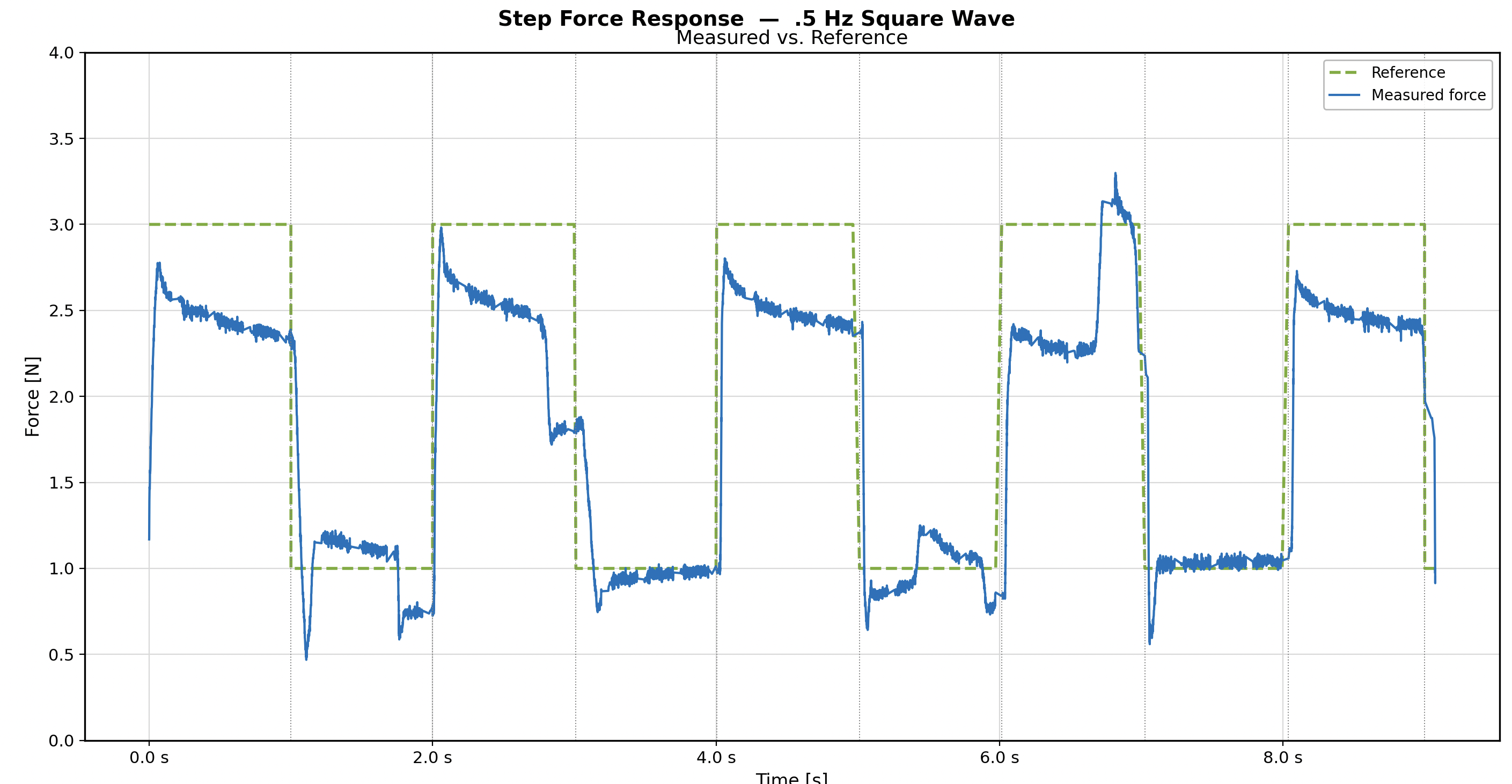
Step Force Control Test
Track a sqaure wave reference force alternating between 1-3 N. at .5 hz. Average Overshoot: 13.64%, Average Steady State Error: .29 N, Average Rise Time: .12 s.
Test 04
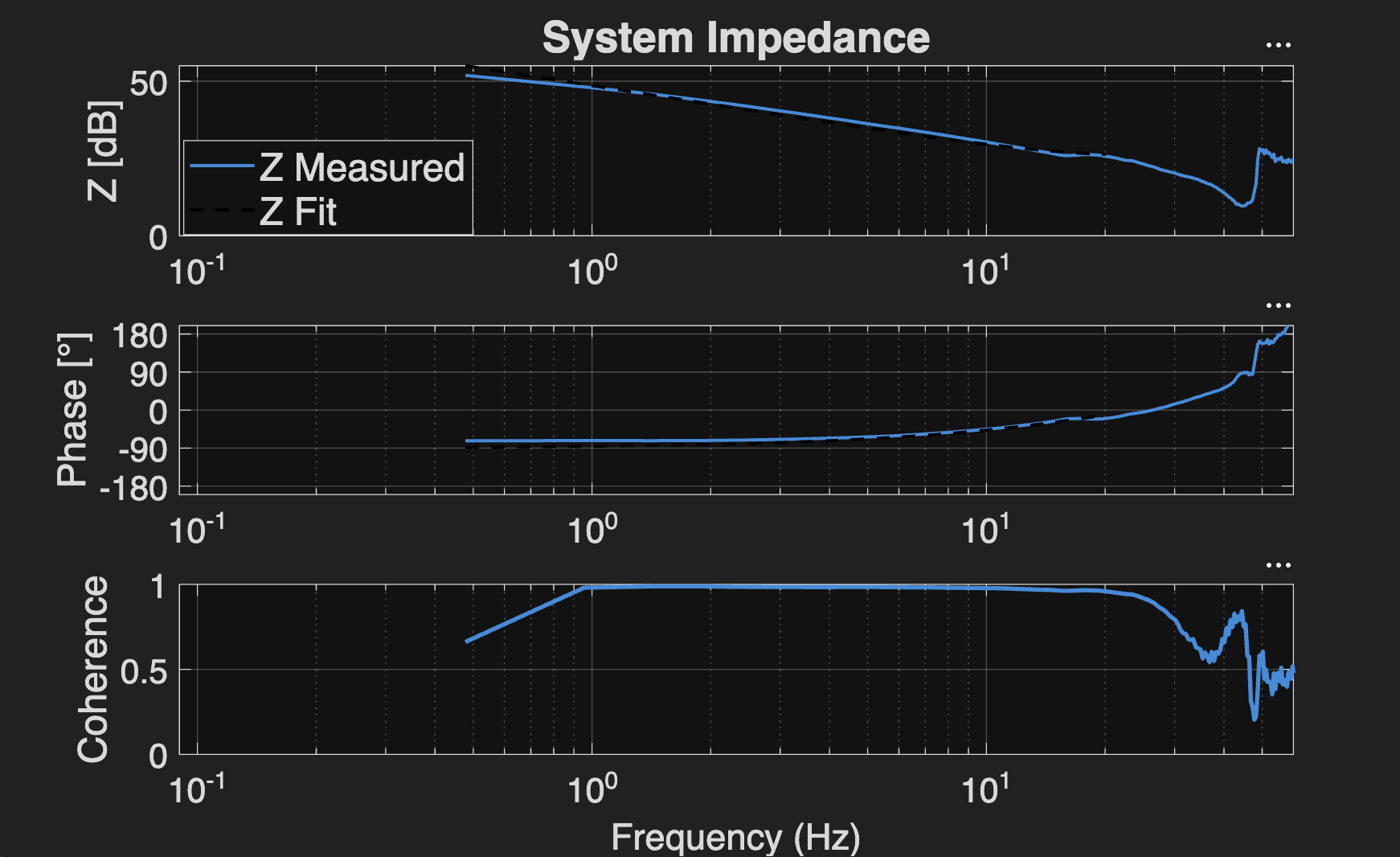
Fingertip Impedance Test (Fully Extended)
With zero control system, externally apply a damping chirp signal up to 50 Hz. From .5 hz. to 20 hz. such that coherence is > .9 Apparent interia = .0728 g, Apparent damping = 20.34 Ns/m, Apparent stiffness = 1687.7 N/m
Test 05
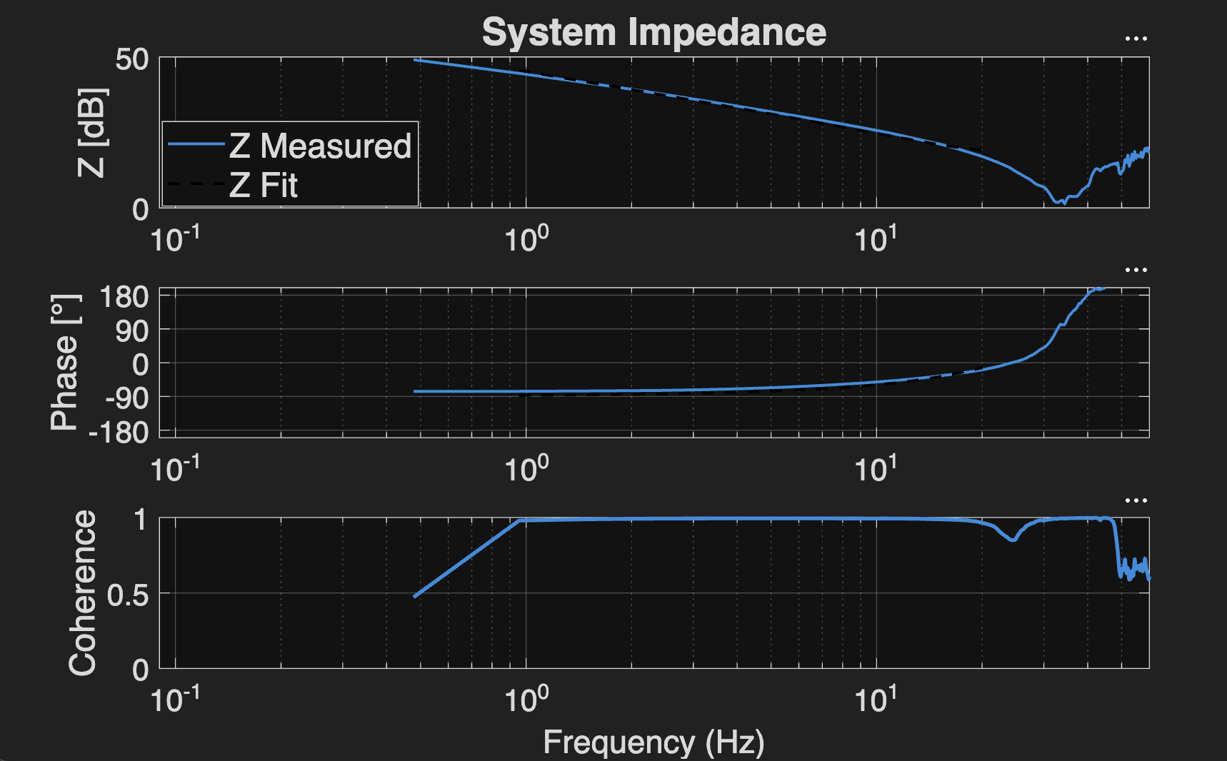
Fingertip Impedance Test (45 degree Flexed)
With zero control system, externally apply a damping chirp signal up to 50 Hz. From 1 hz. to 20 hz. such that coherence is > .9. Apparent interia = .0556 g, Apparent damping = 8.89 Ns/m, Apparent stiffness = 1145.7 N/m
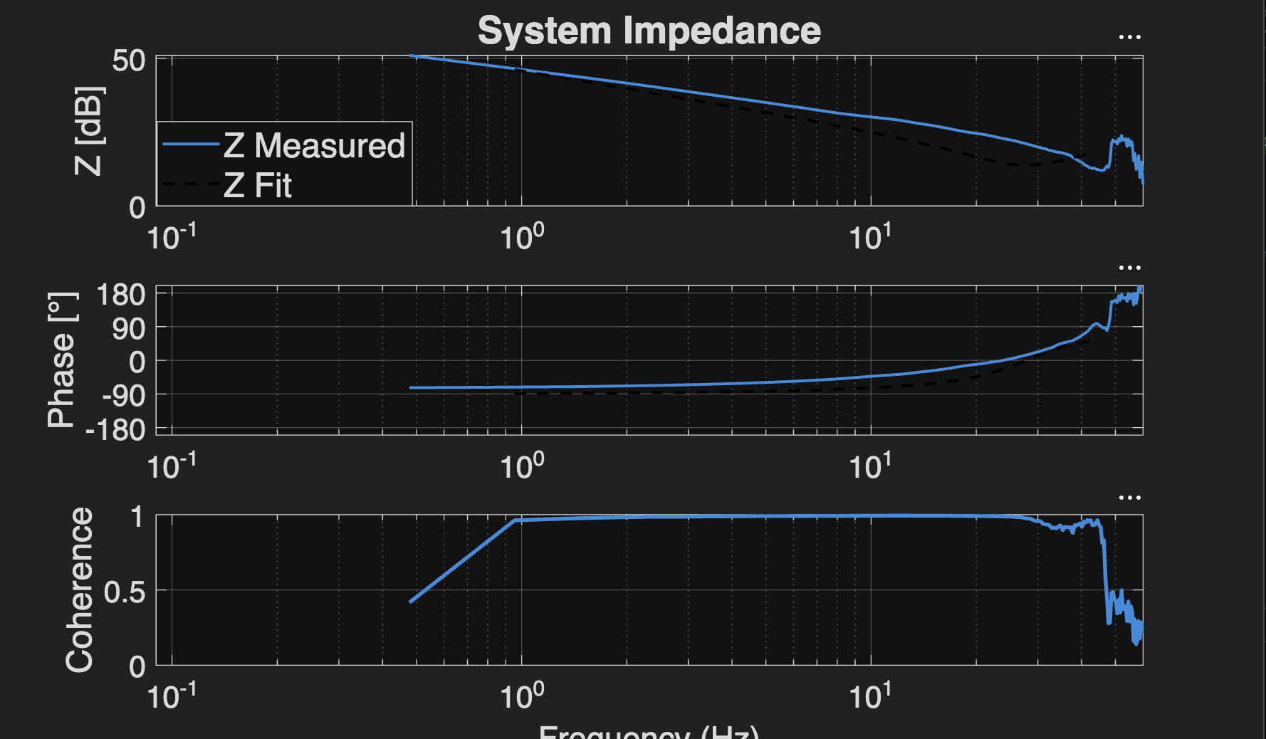
Test 06
Fingertip Impedance Test (Fully Flexed)
With zero control system, externally apply a damping chirp signal up to 50 Hz. From .9 hz. to 35 hz. such that coherence is > .9. Apparent interia = .0402 g, Apparent damping = 4.90 Ns/m, Apparent stiffness = 1227.3 N/m
08 — The Team
Team Surgeon
Aileen Cleary
[ Kinematics Lead ]
Nicholas Melo
[ Design / Manufacturing ]
Andrew Pavlovic
[ Design / Manufacturing]
Julia Xu
[ Electronics / Software ]
Zach Xu
[ Electronics / Software ]


09 — Acknowledgments
Acknowledgments
We are grateful to the following individuals and organizations for their support, guidance, and resources throughout this project.
[ Ed Colgate, Raphael Cherney, Sairam Umakanth ]
Course instruction, design guidance, and technical feedback throughout the design review process.
[ Shop Staff at Ford ]
Manufacturing support, machining guidance, and access to equipment for fabrication.
Northwestern University, CRB, HAND
Funding, laboratory space, and equipment access enabling this research.
[ Other Teams / Collaborators ]
Powerhourse, Speedster, Minimalist Teams for peer feedback during design reviews.
Anthony Shilati for allowing data collection on his testbed.
Soloman from ODrive Support for providing us with the firmware to use the oDrives with our enocoders
10 — References
References
- Feng, Yongfei, et al. "Research on Monocular-Vision-Based Finger-Joint-Angle-Measurement System." Sensors, vol. 22, no. 19, 2022. doi:10.3390/s22197276
- Ornelas, Ruben C., et al. "Everyday finger: a robotic finger that meets the needs of everyday interactive manipulation." 2024 IEEE ICRA, pp. 16016–16023. doi:10.1109/ICRA57147.2024.10611452
- [ Additional references — add as needed ]