Northwestern University | MECH_ENG 472
A tendon-driven robotic finger optimized for strength and durability while preserving speed, range of motion, and functional dexterity.
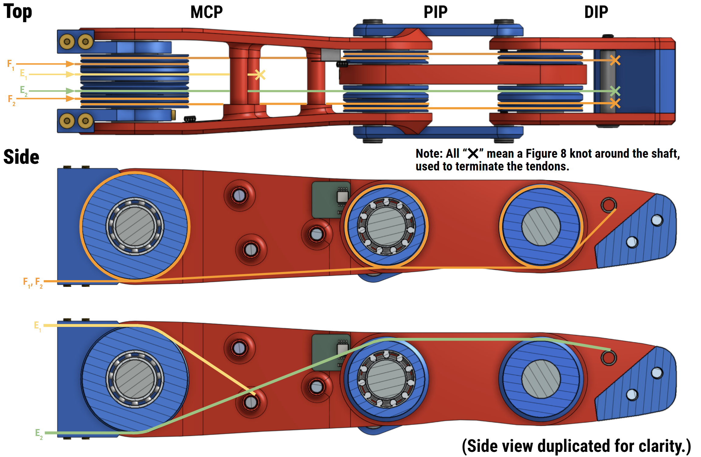
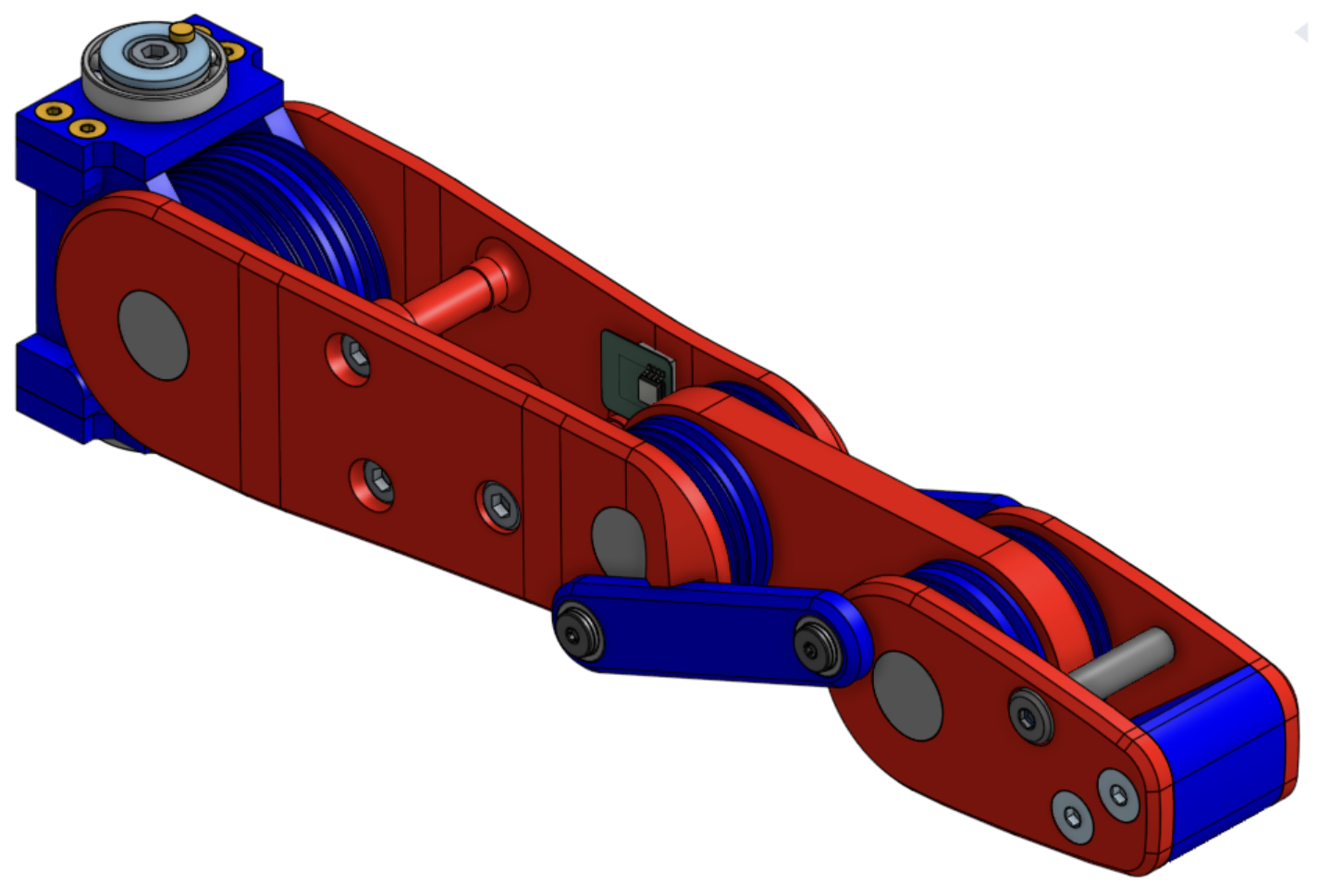
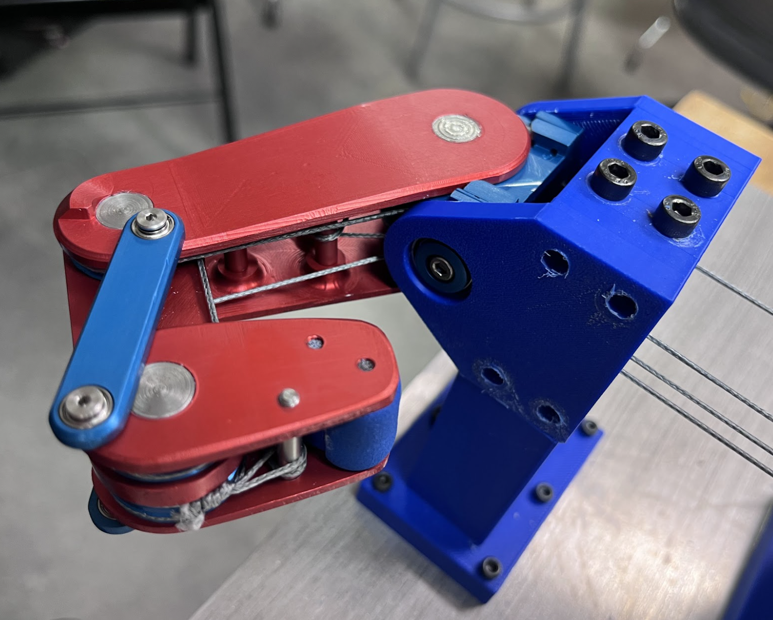
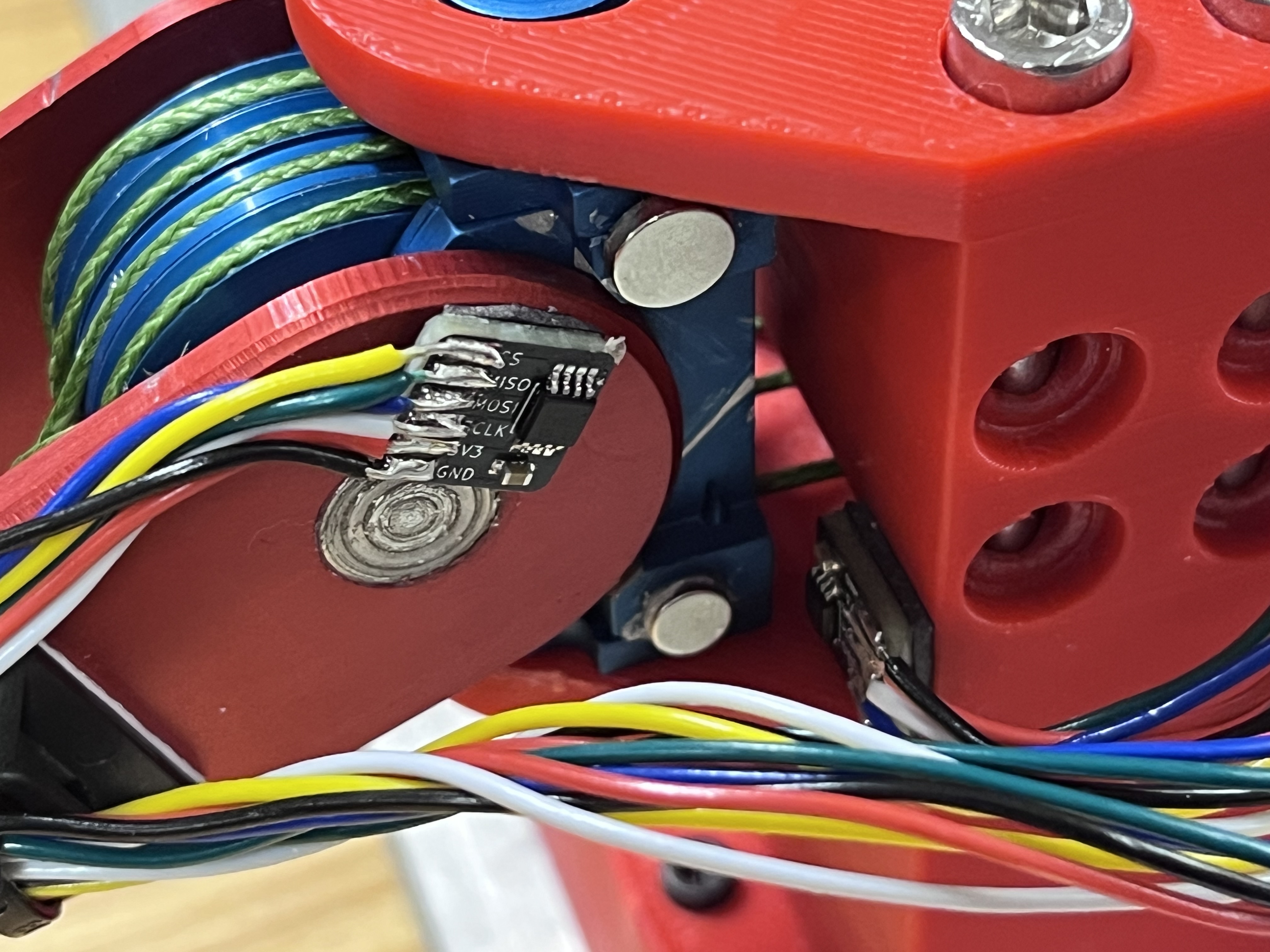
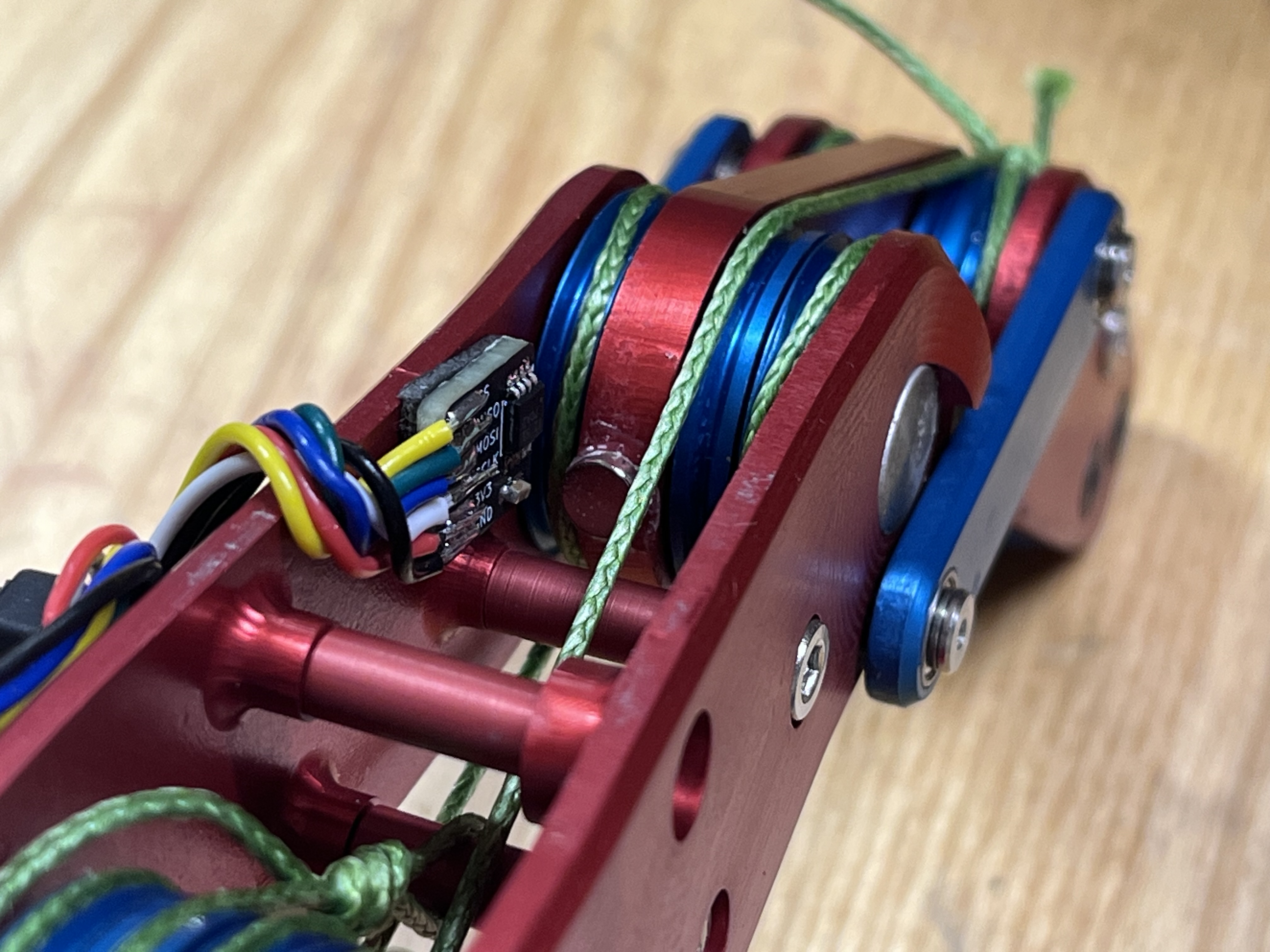
Our capstone team designed a 3-DOF robotic finger focusing on high strength and durability, all without sacrificing practical performance. The final system combines antagonistic tendon routing, coupled finger kinematics, custom pulleys and encoders, and a modular testbed to support robust bench testing and iterative prototyping.
In software and firmware, we built a full stack spanning simulation, controls, teleoperation, and safety-limited embedded motor control. The resulting platform demonstrates repeatable high-load behavior and provides a strong base for future sensing and manipulation tasks.
Michael loses a contest of strength against the Powerhouse finger.
Alternate view of the pencil break demonstration.
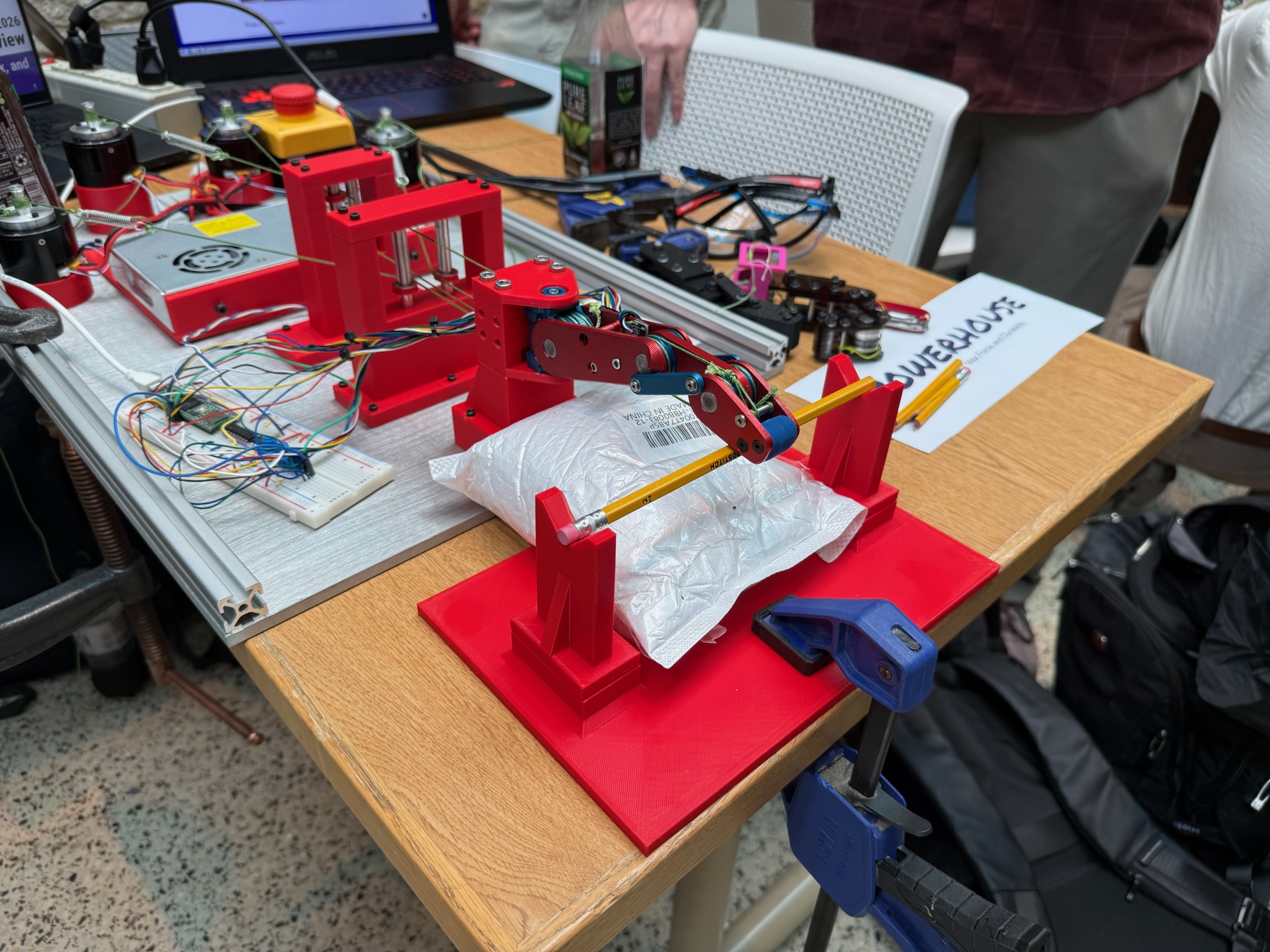
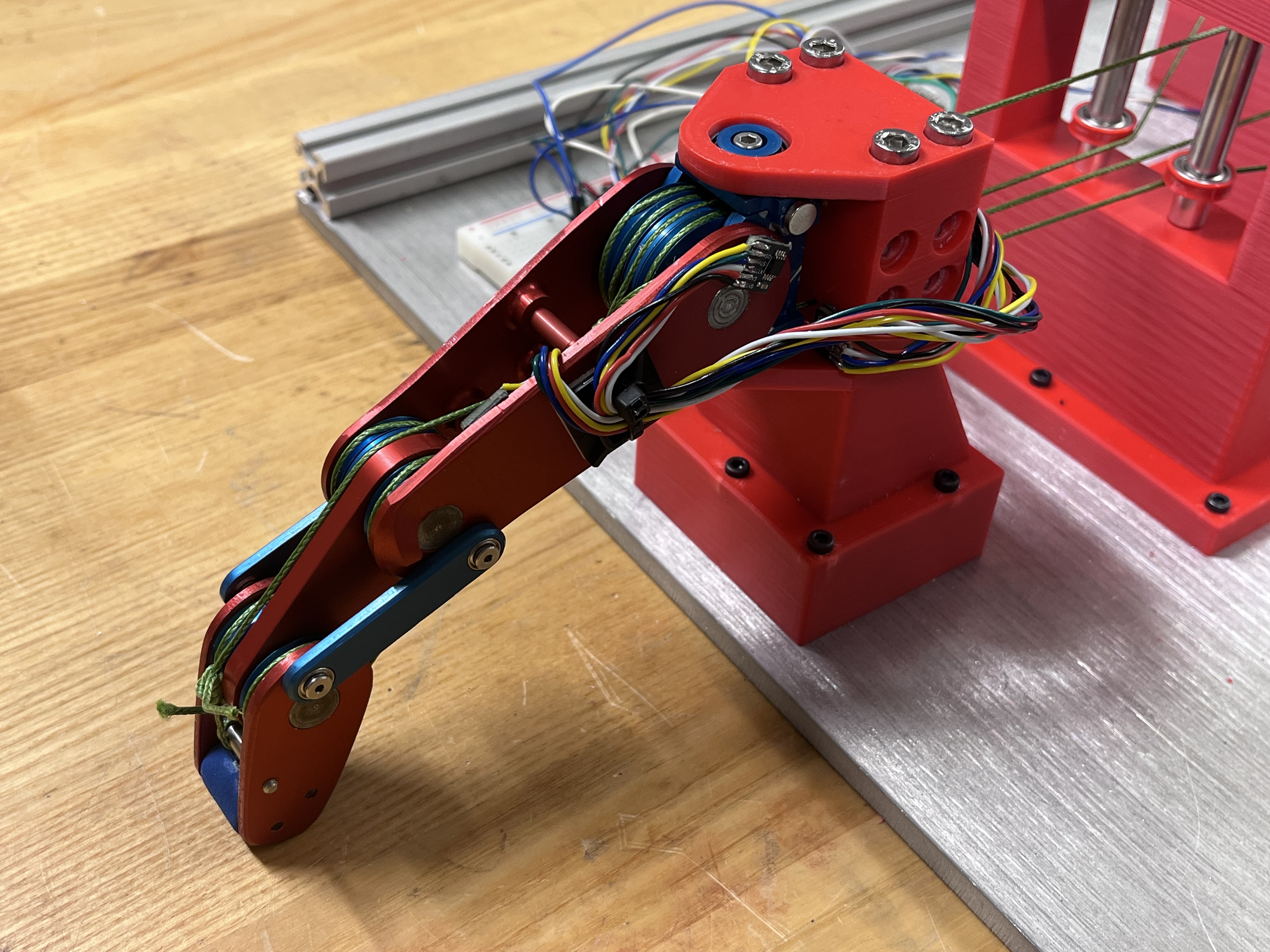
Finger setup at final design showcase.
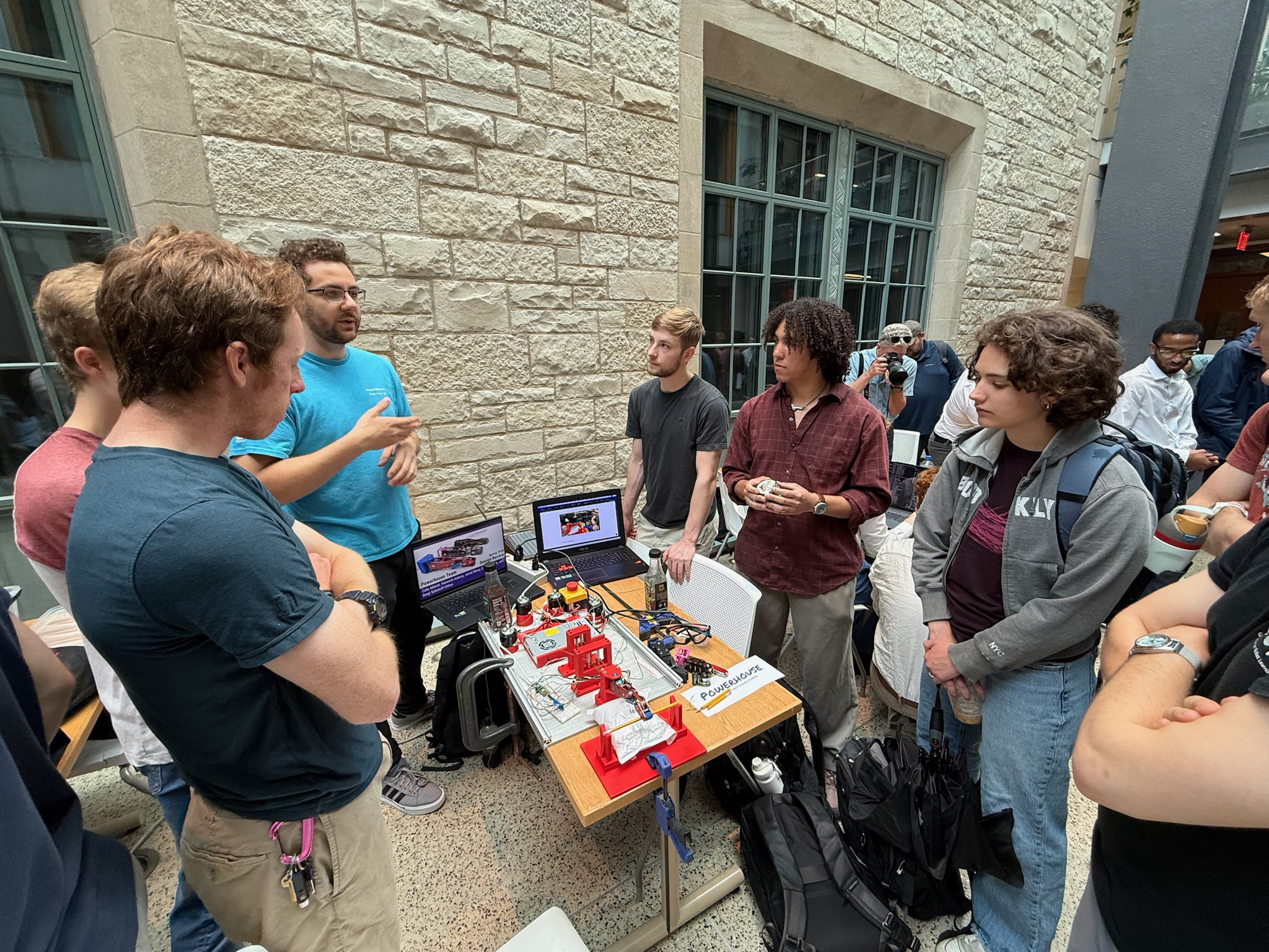
Team Powerhouse running a demo at the final design showcase.
| Metric | Designed / Goal Performance | Actual Performance |
|---|---|---|
| Maximum Output Force at Fingertip (N) | 40 | 103.6 |
| Actuation Speed (RPM) | 15 RPM | >15 RPM |
| MCP Range of Motion (deg) | 90 | 110 |
| PIP Range of Motion (deg) | 90 | 110 |
| DIP Range of Motion (deg) | 90 | 90 |
| Splay Range (deg) | +/- 10 | +/- 20 |
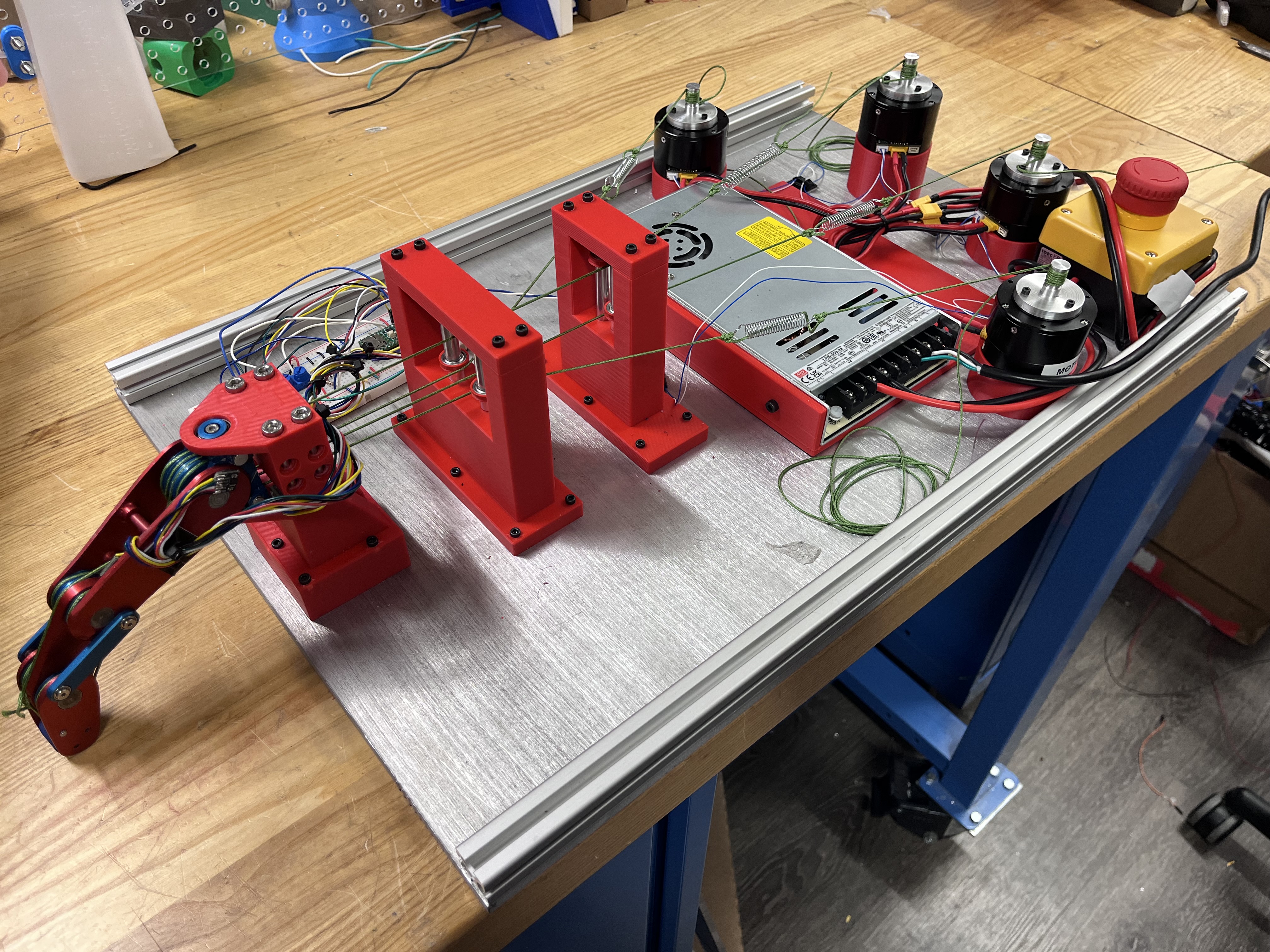
Finger mounted on custom modular testbed.
Side profile view showing resting configuration.
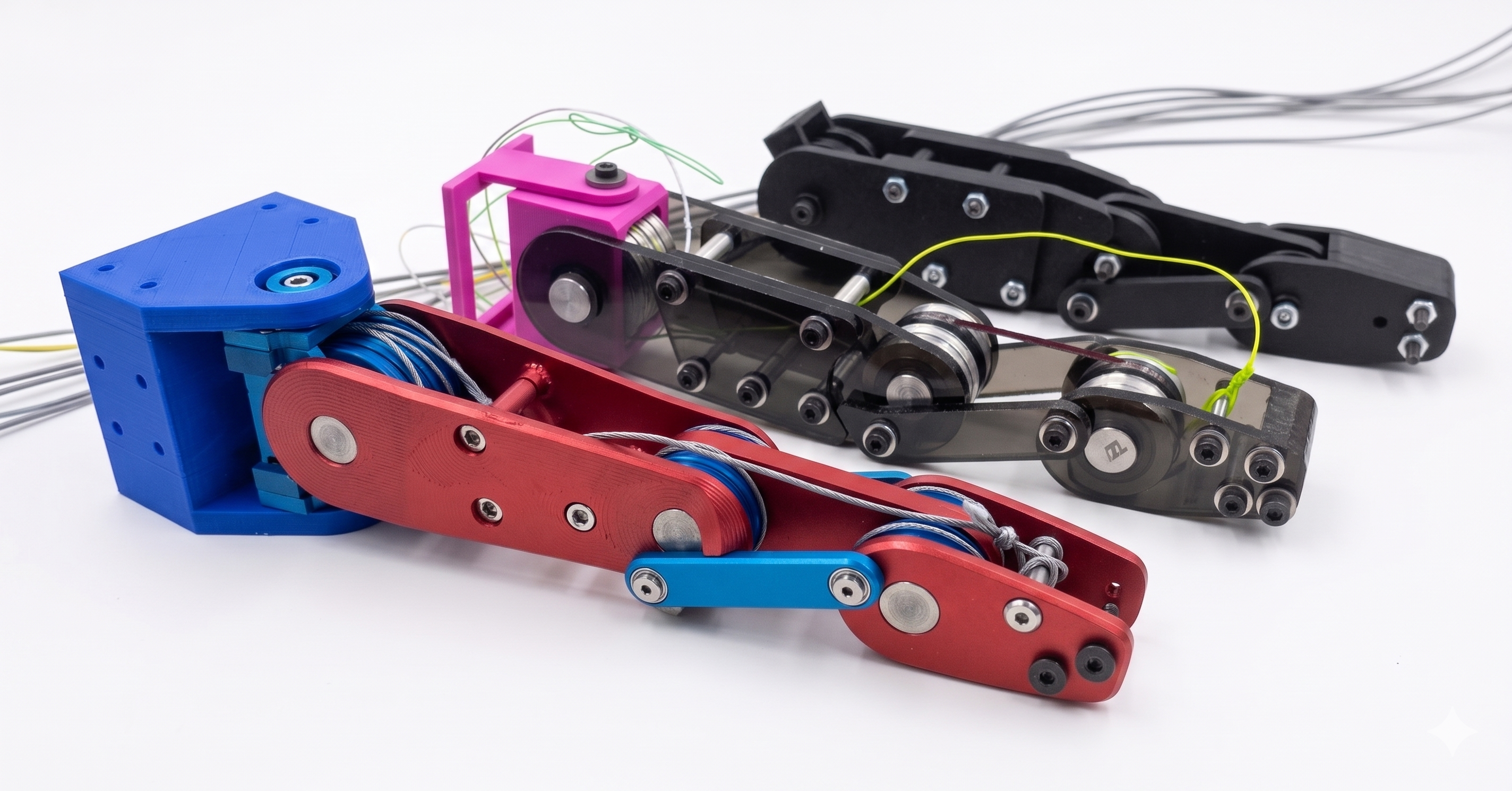
Design iterations used to improve force and durability.
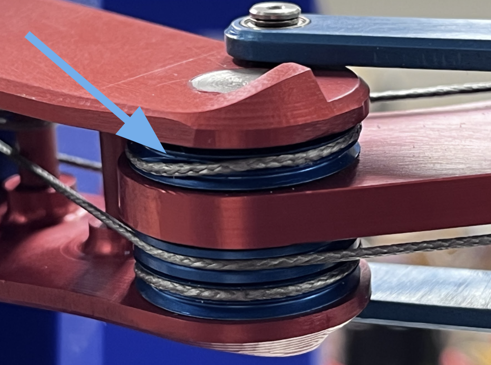
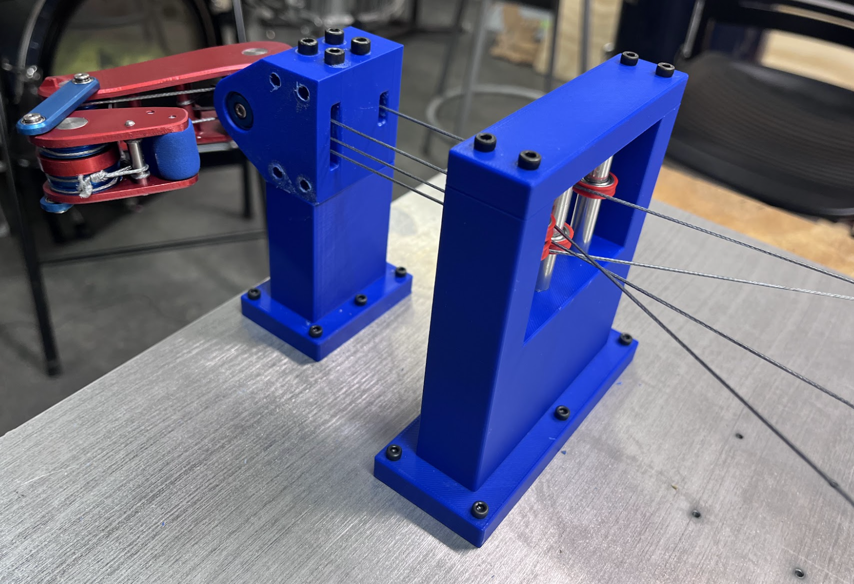
Tendon crossover point on double groove pulley.
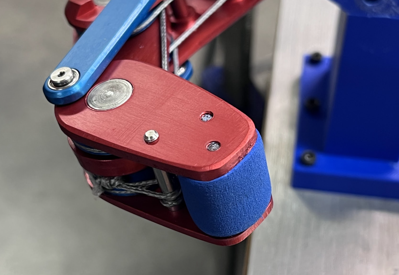
Modular fingertip with integrated compliant surface.
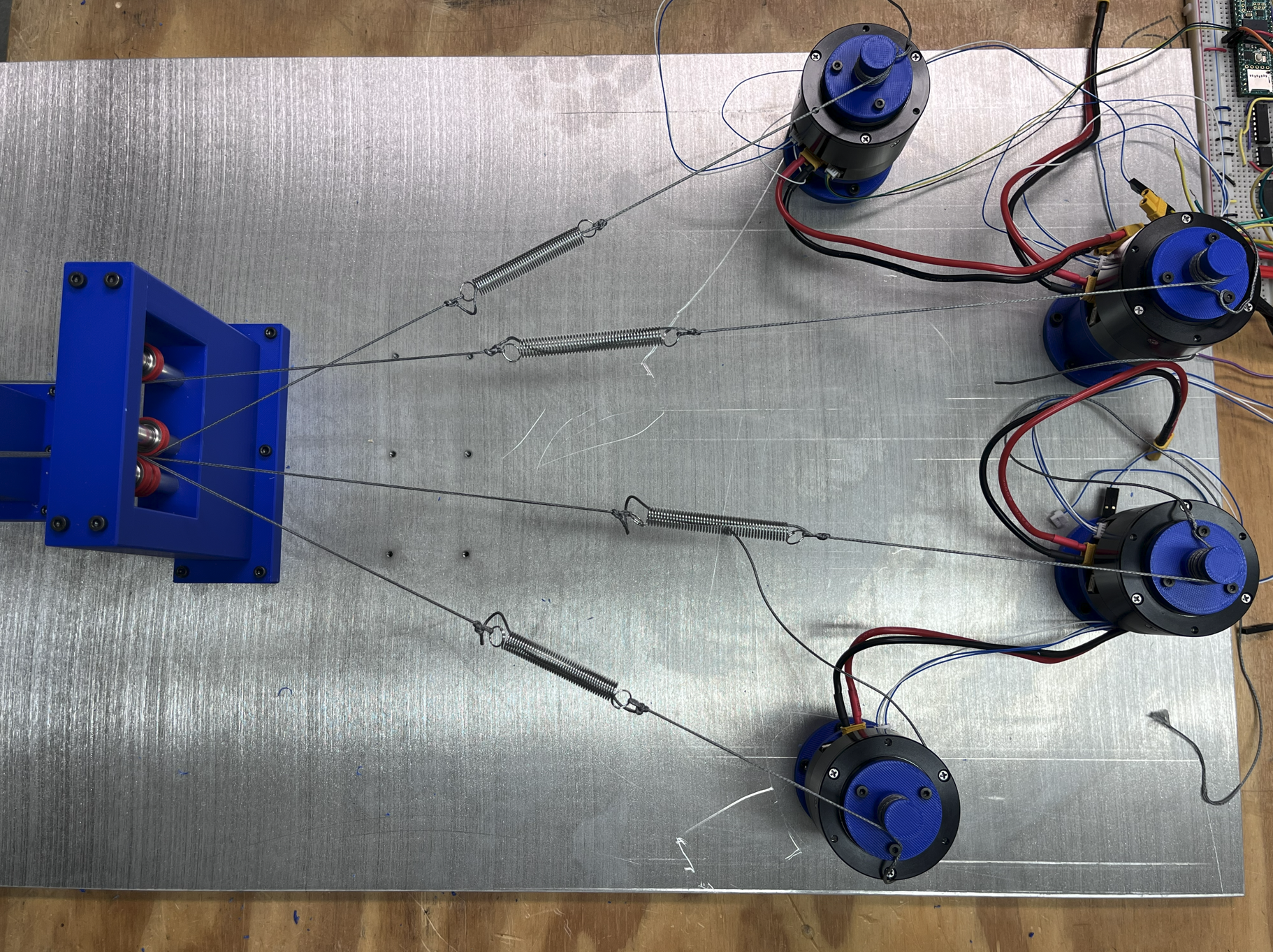
Parallel tensioning springs reduce slack and ease assembly.
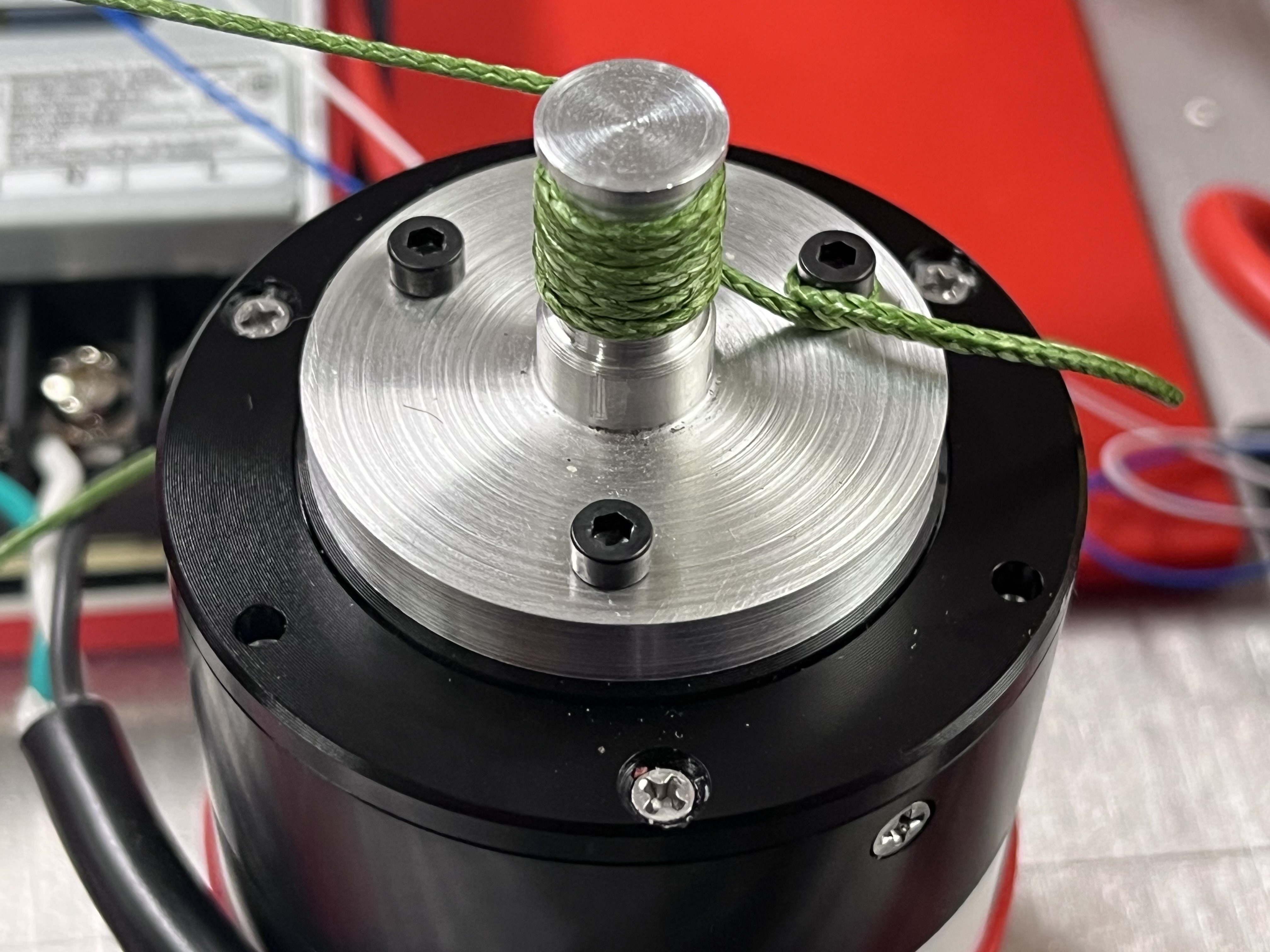
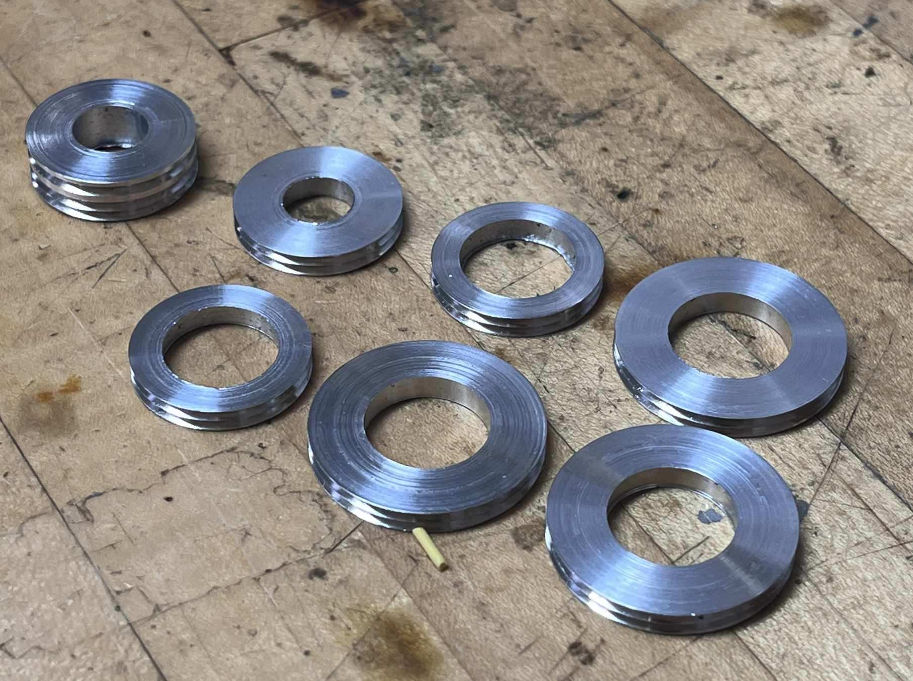
Custom motor pulleys for high torque transmission.
Alternative finger configuration for testing setup.
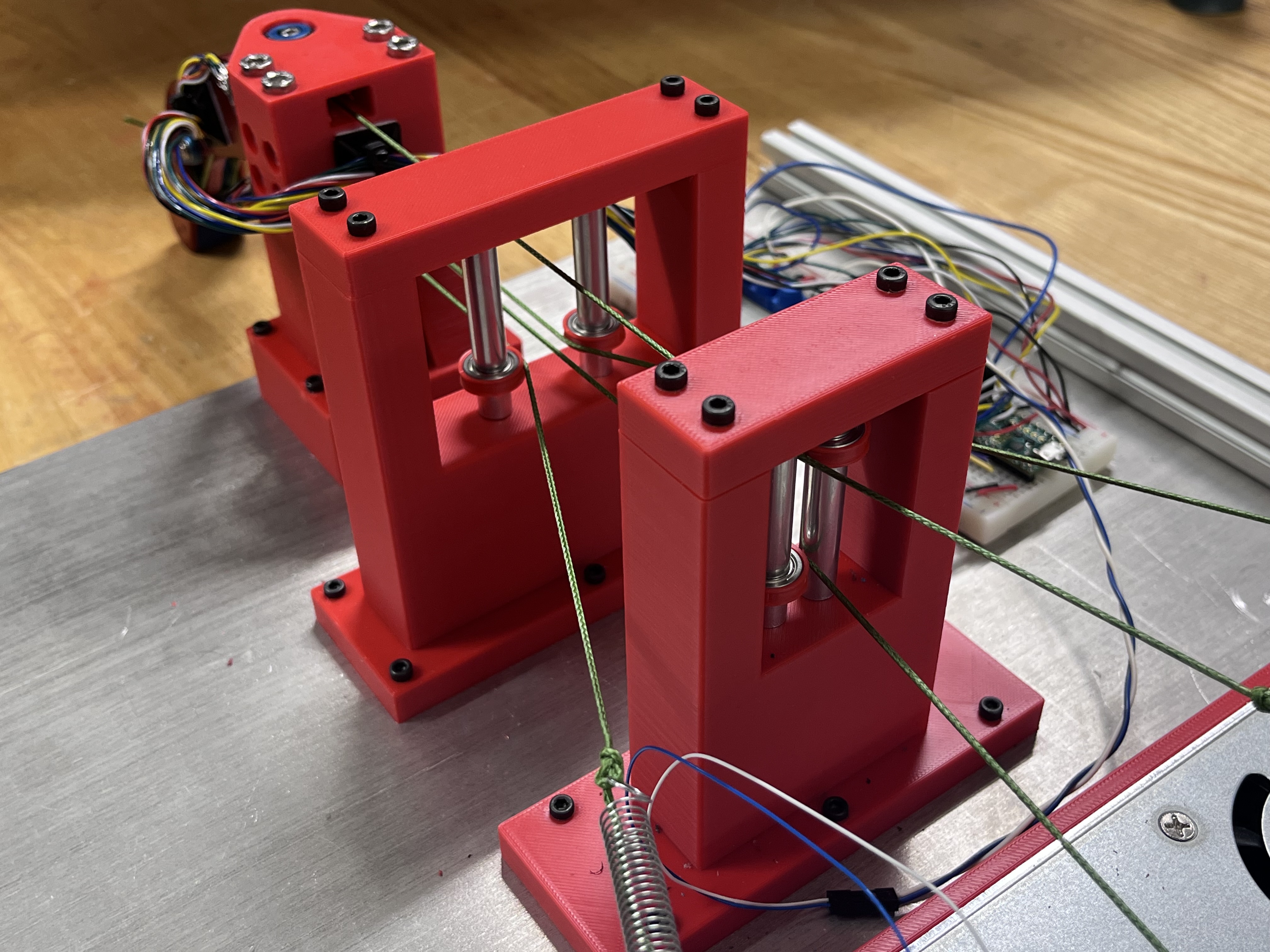
Additional pulley stands for upright configuration.
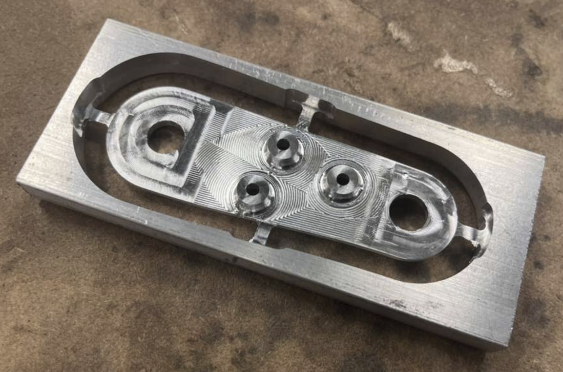
The hardware stack centers on robust tendon routing and modular construction so we can iterate quickly while maintaining high force output and repeatable performance.
| Spec | Value |
|---|---|
| Reduction | 10:1 |
| Continuous Torque (Nm) | 1.3 |
| Stall Torque (Nm) | 4.1 |
| Max Speed (RPM) | 370 |
| Rotor Inertia (gcm²) | 97.35 |
| Back-drive Torque (Nm) | 0.06 |
The firmware and control architecture prioritizes safe torque delivery, reliable sensing, and flexible control interfaces for both bench testing and teleoperation.
Controlled bend sequence under closed-loop operation.
Torque-control teleoperation interface in use.
The simulation toolchain mirrors the physical system, enabling validation of tendon dynamics, inverse kinematics, and controller performance before hardware deployment.
Demo 1: Catapult-style high-force release.
Demo 2: Weighted load interaction.
Demo 3: Fully simulated tendon tension behavior and force-sharing.
Demo 4: Fingertip trajectory tracking with IK.
Software repository: https://github.com/jarmibe7/rds-powerhouse-software
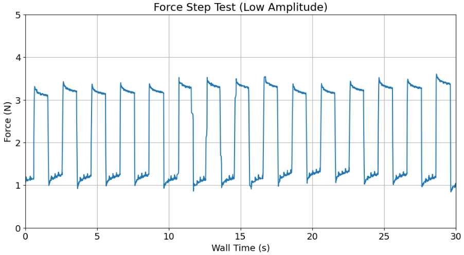
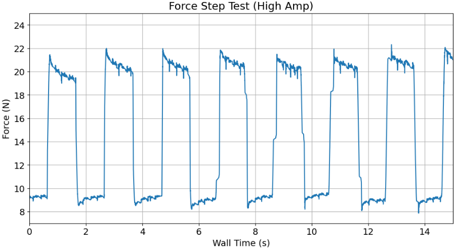
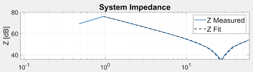
The validation process included impedance response tests, force step tests, and power-focused load tests to verify controller behavior, force capacity, and repeatability against project requirements.
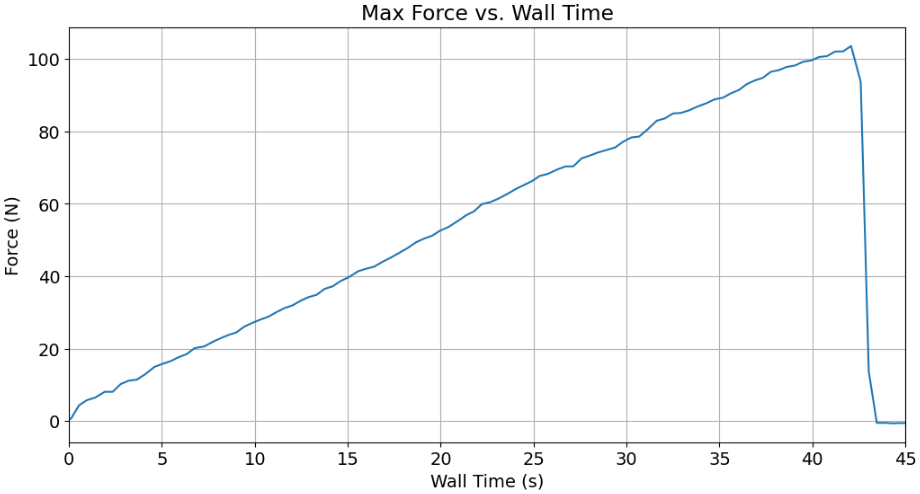
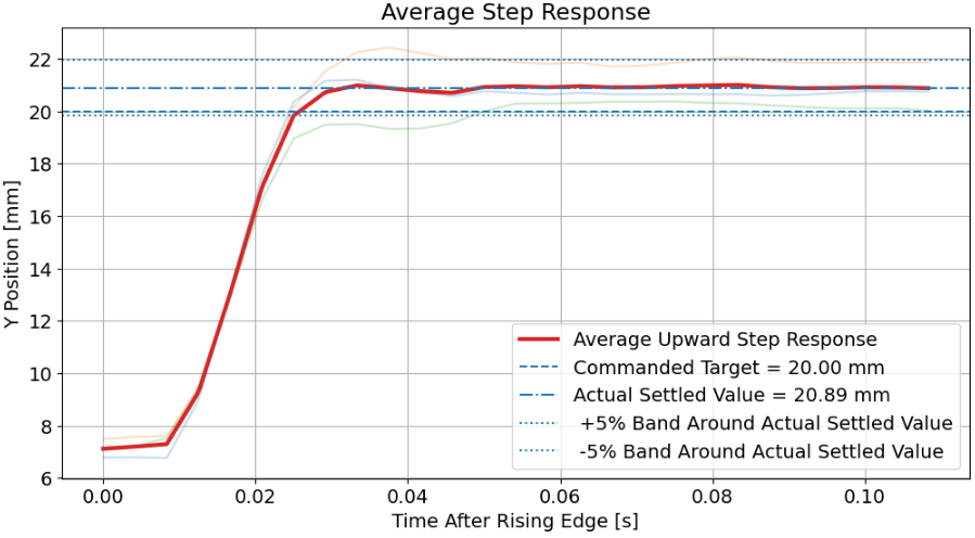
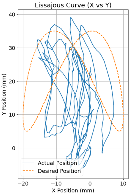
The finger generally performed very well in tests of strength and basic position control, with the max fingertip force far exceeding our design goal and the position step response showing minimal steady state error and settling time. It struggled in the Lissajous trajectory test, which we attribute to a combination of unmodeled dynamics/friction, improper control tuning, and some tendon slack that caused delayed tension delivery. The differential tendon design was a major contributor to the high force output, but it also made the system very sensitive to tuning. The additional noise of the custom encoders also made it difficult to add any derivative gains to the system.
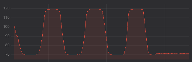
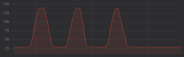
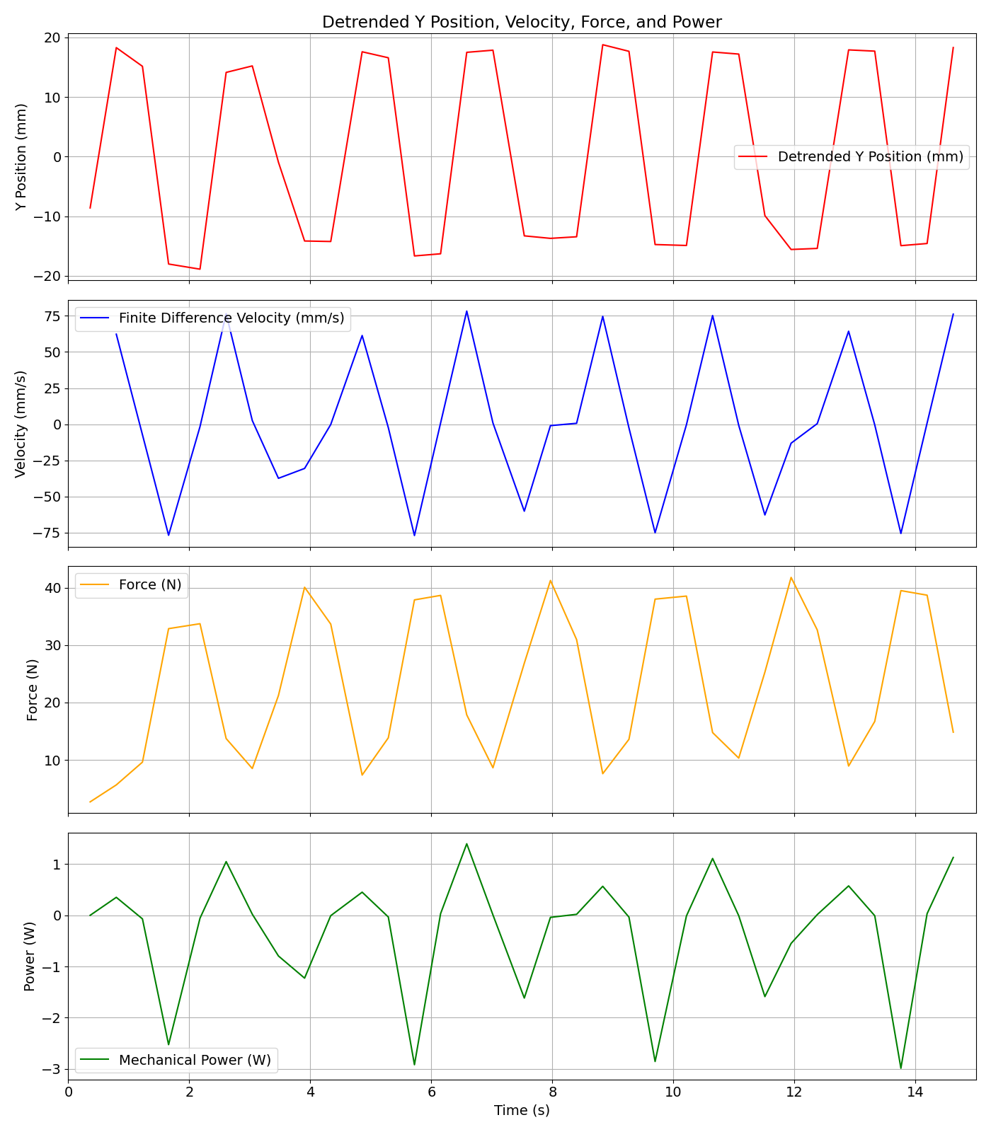
The power output test also had some issues, particularly with the velocity data. We used computer vision to record fingertip position during the test, with the intention of using a finite difference method to calculate instantaneous velocity along the recorded trajectory. However, the finger often moved too quickly for the camera to capture a smooth trajectory, which made the velocity and therefore power calculations very noisy. Despite this, general trends are still present. The power output (negative) increases in magnitude when the force and velocity increase (finger presses down). It also approaches zero when the releases the damper, sometimes even becoming positive. It is possible the positive power is caused by the spring pressing up against the finger when the downward force is released. We also were not able to reach the maximum fingertip speed while constraining the finger in the power output testing setup, meaning the power output is potentiall much lower than the maximum possible. Overall, we are very happy with the performance of the finger, particularly in terms of strength and repeatability, but there are still many opportunities for improvement in control and sensing to enable better performance in dynamic tasks.
| Test Name | Test Goal | Result |
|---|---|---|
| Max. Fingertip Force | Apply high forces to the environment. | 103.6 N |
| Force Step Response - Low Magnitude (2 N Amp.) | Determine the force response under low load conditions. | See plot below. |
| Force Step Response - High Magnitude (10 N Amp.) | Determine the force response under high load conditions. | See plot below. |
| Finger Impedance Test | Determine the impedance characteristics of the finger. | See plot below. |
| Position Step Response - Steady State Error | Measure the average steady state error under position step commands. | 1.12 mm |
| Position Step Response - Overshoot | Measure the average overshoot under position step commands. | 19.36% |
| Position Step Response - Average Settling Time | Measure the average 5% settling time per step under position step commands. | 0.0333 s |
| Lissajous Trajectory Response - Integrated Error | Measure the integrated error under while the fingertip follows a Lissajous trajectory. | 61.4320 mm*s |
| Power Test | Evaluate sustained high-load operation with average mechanical power output. | 0.7297 W |
| Item | Qty | Unit Cost (USD) | Total Cost (USD) | Type | Description |
|---|---|---|---|---|---|
| 10x19x5 mm Steel Ball Bearing | 2 | $7.20 | $14.40 | Stock Component | PIP, DIP Bearing |
| 10x15x3 mm Steel Ball Bearing | 10 | $11.66 | $116.60 | Stock Component | Pulley and universal bearing |
| 10x12x0.5, x0.2, and x0.1 Shim | 14 | $11.97 | $23.94 | Stock Component | Shims for Pulleys (2x variety pack) |
| Hex socket head cap screw M3x0.50 x 18 | 3 | $0.0 | $15.26 | Stock Component | Member 1 Bolts, 100 Pack |
| Hall Sensor PCB | 3 | $2.21 | $6.63 | Stock Component | N/A |
| 3x7x3 mm Stainless Steel Ball Bearing | 4 | $8.26 | $33.04 | Stock Component | Linkage Bearing |
| 3mm ID 5mm OD x 0.5mm Washer | 8 | $0.0 | $5.99 | Stock Component | Linkage Washer |
| Ultra-Low-Profile Precision Shoulder Screw | 4 | $4.22 | $16.88 | Stock Component | N/A |
| M3x20 Bolt | 2 | $0.0 | $14.47 | Stock Component | 100 Pack |
| 3mm Shoulder Bolt | 1 | $8.68 | $8.68 | Stock Component | N/A |
| Hex socket head cap screw M3x0.50 x 4 | 2 | $0.0 | $13.80 | Stock Component | 100 Pack |
| Hex socket head cap screw M2x0.40 x 5 | 2 | $0.0 | $18.48 | Stock Component | 100 Pack |
| Hex drive flat head screw M2x0.40 x 5 | 8 | $0.0 | $9.60 | Stock Component | 50 Pack |
| Neodymium Magnet | 3 | $0.81 | $2.43 | Stock Component | N/A |
| Cubemars Motors | 4 | $185.00 | $740.00 | Stock Component | N/A |
| Tendon Material | 1 | $18.99 | $18.99 | Stock Component | N/A |
| Multipurpose Aluminum Stock | 1 | $50.00 | $50.00 | Stock Component | Bar stock for custom parts |
| Aluminum Baseplate | 1 | $141.23 | $141.23 | Stock Component | Baseplate for finger mounting |
| 0603 (1608 metric) Multilayer Ceramic Capacitors | 2 | $0.0 | $0.0 | Stock Component | In House |
| 10mm Shaft Stock | 1 | $10.18 | $10.18 | Stock Component | 200mm Length |
| Member 2 | 1 | $0.0 | $0.0 | Mill | In House |
| Linkage | 2 | $0.0 | $0.0 | Mill | In House |
| Member 3 Right | 1 | $0.0 | $0.0 | Mill | In House |
| Member 3 Left | 1 | $0.0 | $0.0 | Mill | In House |
| Universal Plate | 1 | $0.0 | $0.0 | Mill | In House |
| Universal Body | 1 | $0.0 | $0.0 | Mill | In House |
| Base | 1 | $0.0 | $0.0 | Mill | In House |
| DIP Shaft | 1 | $0.0 | $0.0 | Lathe | In House |
| PIP Shaft | 1 | $0.0 | $0.0 | Lathe | In House |
| MCP Shaft | 1 | $0.0 | $0.0 | Lathe | In House |
| 22mm 1 Grove Pulley | 1 | $0.0 | $0.0 | Lathe | In House |
| 22mm 10mm Double Grove Pulley | 1 | $0.0 | $0.0 | Lathe | In House |
| 22mm Double Grove Pulley | 2 | $0.0 | $0.0 | Lathe | In House |
| 22mm Triple Grove Pulley | 1 | $0.0 | $0.0 | Lathe | In House |
| 28mm Double Grove Pulley | 3 | $0.0 | $0.0 | Lathe | In House |
| 28 mm Single Grove Pulley | 1 | $0.0 | $0.0 | Lathe | In House |
| Member 1 Spacer | 3 | $0.0 | $0.0 | Lathe | In House |
| Universal Spacer | 2 | $0.0 | $0.0 | Lathe | In House |
| Member 1 Right | 1 | $0.0 | $0.0 | CNC | In House |
| Member 1 Left | 1 | $0.0 | $0.0 | CNC | In House |
| PIP Encoder Mount | 1 | $0.0 | $0.0 | 3D Print | In House |
| Fingertip | 1 | $0.0 | $0.0 | 3D Print | In House |
| Total | $1240.82 |
CAD File: https://cad.onshape.com/documents/9008e8e00ba75713bd9082d6 Thank you to Dr. Colgate, Raphael, and Sairam Umakanth for their guidance throughout the entire design process. We also thank shop faculty, guest reviewers, and Tony Shilati, all for assisting us with design, manufacturing, and testing on their personal time. Lastly, thank you to our peers in RDS for their helpful feedback and support along the way!